Nissan Titan. Instruction - part 137


  Index      Nissan     Nissan Titan (2014 year) - Service and Repair Instruction


Search            copyright infringement  


Content   ..  135  136  137  138   ..


Nissan Titan. Instruction - part 137


DLN-120

< UNIT DISASSEMBLY AND ASSEMBLY >

[TRANSFER: TX15B]

PLANETARY CARRIER

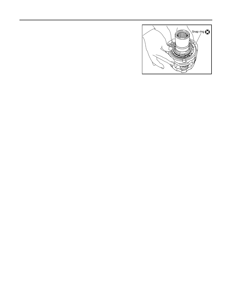
5. Install the sun gear assembly to the planetary carrier assembly.
6. Install the new snap ring to the planetary carrier assembly.

CAUTION:

Do not reuse snap ring.

SDIA2794E

FRONT DRIVE SHAFT

DLN-121

< UNIT DISASSEMBLY AND ASSEMBLY >

[TRANSFER: TX15B]

C

E

F

G

H

I

J

K

L

M

A

B

DLN

N

O

P

FRONT DRIVE SHAFT

Disassembly and Assembly

INFOID:0000000009886041

DISASSEMBLY

1. Remove the front bearing using Tools.

2. Remove the rear bearing using Tools.

INSPECTION AFTER DISASSEMBLY

Front Drive Shaft

Check the items below. If necessary, replace them with new ones.

• Damage, peeling, dent, uneven wear and bending of the shaft.

• Excessive wear, damage and peeling of the gear.

Bearing

Check the bearing for damage and rough rotation. If necessary,

replace the bearing with a new one.

ASSEMBLY

Tool number

(A): ST35300000 ( — )
(B): ST30021000 (J-22912-01)

SDIA2106E

Tool number

(A): ST33710000 ( — )
(B): ST30021000 (J-22912-01)

PDIA0153E

PDIA0154E

MTF0041D

DLN-122

< UNIT DISASSEMBLY AND ASSEMBLY >

[TRANSFER: TX15B]

FRONT DRIVE SHAFT

1. Install the rear bearing using Tools.

2. Install the front bearing using Tools.

Tool number

(A): KV38100500 ( — )
(B): ST30901000 (J-26010-01)

PDIA0155E

Tool number

(A): KV38100500 ( — )
(B): ST30901000 (J-26010-01)

PDIA0156E

SHIFT CONTROL

DLN-123

< UNIT DISASSEMBLY AND ASSEMBLY >

[TRANSFER: TX15B]

C

E

F

G

H

I

J

K

L

M

A

B

DLN

N

O

P

SHIFT CONTROL

Disassembly and Assembly

INFOID:0000000009886042

DISASSEMBLY

1. Remove the snap ring.

CAUTION:

Do not reuse snap ring.

2. Remove the retaining pin. 

CAUTION:

Do not reuse retaining pin.

3. Remove the drum cam from the control shift rod.

4. Remove the retaining pin from the L-H shift rod.

CAUTION:

Do not reuse retaining pin.

5. Remove the 2-4 shift bracket.

6. Remove the retaining ring from the 2-4 shift fork using suitable

tool.

CAUTION:

Do not reuse retaining ring.

7. Remove the fork guide collar and 2-4 shift fork spring from the 2-

4 shift fork.

INSPECTION AFTER DISASSEMBLY

Shift Fork

• Measure the clearance between the shift fork and sleeve. If it is out

of specification, replace it with a new one.

Shift Rod and Fork Components

PDIA0122E

PDIA0125E

WDIA0226E

Standard value
2-4

: Less than 0.46 mm (0.018 in)

L-H

: Less than 0.46 mm (0.018 in)

PDIA0134E


Content   ..  135  136  137  138   ..