Nissan Titan. Instruction - part 132


  Index      Nissan     Nissan Titan (2014 year) - Service and Repair Instruction


Search            copyright infringement  


Content   ..  130  131  132  133   ..


Nissan Titan. Instruction - part 132


DLN-100

< UNIT REMOVAL AND INSTALLATION >

[TRANSFER: TX15B]

TRANSFER ASSEMBLY

UNIT REMOVAL AND INSTALLATION

TRANSFER ASSEMBLY

Removal and Installation

INFOID:0000000009886038

NOTE:

When removing components such as hoses, tubes/lines, etc., cap or plug openings to prevent fluid from spill-

ing.

REMOVAL

1. Switch 4WD shift switch to 2WD and set transfer assembly to 2WD.
2. Remove the under covers using power tool.
3. Partially drain the transfer fluid. Refer to 

DLN-89, "Replacement"

.

4. Remove the center exhaust tube and main muffler. Refer to 

EX-5, "Removal and Installation"

.

5. Remove the front and rear propeller shafts. Refer to 

DLN-130, "Removal and Installation"

 (front), 

DLN-

139, "Removal and Installation"

 (rear).

CAUTION:

Do not damage spline, sleeve yoke and rear oil seal when removing rear propeller shaft.

6. Remove the A/T nuts from the A/T crossmember. Refer to 

TM-213, "Removal and Installation (4WD)"

.

7. Position two suitable jacks under the A/T and transfer assembly.
8. Remove the A/T crossmember. Refer to 

TM-213, "Removal and Installation (4WD)"

.

WARNING:

Support A/T and transfer assembly using two suitable jacks while removing A/T crossmember.

9. Disconnect the harness connectors from the following:

• ATP  switch

• 4LO switch

• Wait detection switch

• Transfer control device

10. Disconnect each air breather hose from the following. Refer to 

DLN-98, "Removal and Installation"

.

• Transfer control device

• Breather tube (transfer)

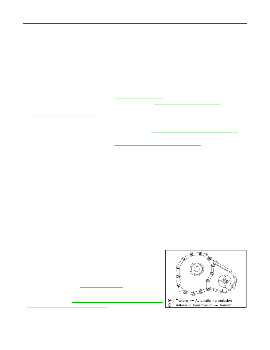
11. Remove the transfer to A/T and A/T to transfer bolts.
12. Remove the transfer assembly.

WARNING:

Support transfer assembly with suitable jack while removing it.

CAUTION:

Do not damage rear oil seal (A/T).

INSTALLATION

Installation is in the reverse order of removal.

• Tighten the bolts to specification.

• Fill the transfer with new fluid and check for fluid leaks and fluid

level. Refer to 

DLN-89, "Inspection"

.

• Start the engine for one minute. Then stop the engine and recheck

the transfer fluid. Refer to 

DLN-89, "Inspection"

.

• After the installation, check the 4WD shift indicator pattern. If NG,

adjust the position between the transfer assembly and transfer

control unit. Refer to 

DLN-82, "Precaution for Transfer Assembly

and Transfer Control Unit Replacement"

.

Tightening torque

: 36 N·m (3.7 kg-m, 27 ft-lb)

SMT872C

TRANSFER ASSEMBLY

DLN-101

< UNIT DISASSEMBLY AND ASSEMBLY >

[TRANSFER: TX15B]

C

E

F

G

H

I

J

K

L

M

A

B

DLN

N

O

P

UNIT DISASSEMBLY AND ASSEMBLY

TRANSFER ASSEMBLY

Disassembly and Assembly

INFOID:0000000009886039

COMPONENTS

1.

Baffle plate

2.

Breather tube

3.

Front case

4.

Snap ring

5.

Input oil seal

6.

Self-lock nut

7.

Companion flange

8.

Front oil seal

9.

4LO switch (gray with green paint)

10. ATP switch (black)

11. Rear case

12. Wait detection switch (gray)

13. Gasket

14. Filler plug

15. Drain plug

16. O-ring

17. Transfer control device

18. Harness bracket

19. Dust cover

20. Oil cover

21. Rear oil seal

22. Air breather hose clamp

23. Retainer bolt

24. Gasket

A.

Apply Genuine Anaerobic Liq-
uid Gasket or equivalent.

B.

Apply Genuine Silicone 
RTV or equivalent.

P.

Apply petroleum jelly

AWDIA0749GB

DLN-102

< UNIT DISASSEMBLY AND ASSEMBLY >

[TRANSFER: TX15B]

TRANSFER ASSEMBLY

DISASSEMBLY

1. Remove the drain plug and filler plug.

1.

Input bearing

2.

Snap ring

3.

Internal gear

4.

Carrier bearing

5.

Sun gear

6.

Needle bearing

7.

Metal bushing

8.

Planetary carrier assembly

9.

L-H sleeve

10. Drive chain

11. Mainshaft

12. Sprocket

13. 2-4 sleeve

14. Clutch gear

15. Oil pump assembly

16. Retainer

17. Mainshaft rear bearing

18. Front bearing

19. Front drive shaft

20. Rear bearing

21. L-H shift fork

22. L-H shift rod

23. Retaining pin

24. 2-4 shift bracket

25. 2-4 shift fork

26. Fork guide collar

27. 2-4 shift fork spring

28. Retaining ring

29. Snap ring

30. Shift collar

31. Clevis pin

32. Drum cam

33. Control shift rod

34. Spacer

AWDIA0016GB

TRANSFER ASSEMBLY

DLN-103

< UNIT DISASSEMBLY AND ASSEMBLY >

[TRANSFER: TX15B]

C

E

F

G

H

I

J

K

L

M

A

B

DLN

N

O

P

2. Remove the transfer control device from the rear case.
3. Remove the O-ring from the transfer control device.

CAUTION:

Do not reuse O-ring.

4. Remove the self-lock nut from the companion flange using suit-

able tool.

5. Put a matching mark on top of the front drive shaft in line with

the mark on the companion flange.

CAUTION:

Use paint to make the matching mark on the front drive

shaft. Do not damage the front drive shaft.

6.  Remove the companion flange using suitable tool.

7. Remove the front oil seal from the front case using Tool.

CAUTION:

Do not damage front case or front drive shaft.

SDIA2212E

SDIA2841E

SDIA2779E

WDIA0133E

Tool number

: ST33290001 (J-34286)

SDIA2423E


Content   ..  130  131  132  133   ..