Nissan Cube. Instruction - part 860
IPDM E/R (INTELLIGENT POWER DISTRIBUTION MODULE ENGINE ROOM)
SEC-251
< ECU DIAGNOSIS INFORMATION >
[WITHOUT INTELLIGENT KEY SYSTEM]
C
D
E
F
G
H
I
J
L
M
A
B
SEC
N
O
P
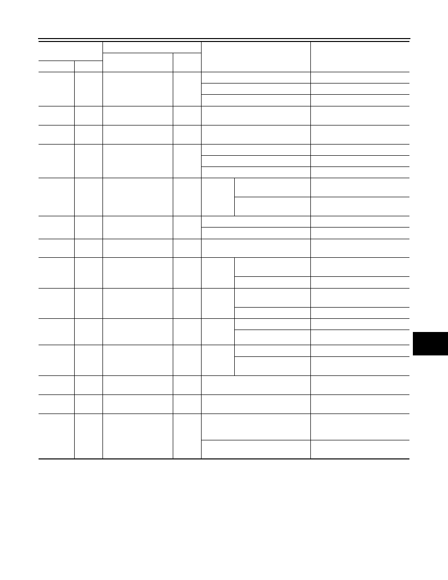
7
(Y)
Ground
Cooling fan relay-2
power supply
Output
Cooling fan OFF
0 V
Cooling fan LO operated
9.0 V
Cooling fan HI operated
Battery voltage
8
(V)
Ground
Battery power supply
Input
Ignition switch OFF
Battery voltage
9
(B/W)
Ground
Ground
—
Ignition switch ON
0 V
10
(L)
Ground
Cooling fan motor
ground
Output
Cooling fan OFF
0 V
Cooling fan LO operated
5.0 V
Cooling fan HI operated
0 V
13
(W)
Ground
Rear window defogger
Output
Ignition
switch
ON
Rear window defogger
switch OFF
0 V
Rear window defogger
switch ON
Battery voltage
18
(Y)
Ground
Ignition switch
Output
Ignition switch OFF
0 V
Ignition switch ON
Battery voltage
19
(B/W)
Ground
Ground
—
Ignition switch ON
0 V
21
(W)
Ground
Front fog lamp (RH)
Output
Lighting
switch
2ND
Front fog lamp switch
OFF
0 V
Front fog lamp switch ON
Battery voltage
22
(V)
Ground
Front fog lamp (LH)
Output
Lighting
switch
2ND
Front fog lamp switch
OFF
0 V
Front fog lamp switch ON
Battery voltage
24
(G)
Ground
Oil pressure switch
Input
Ignition
switch
ON
Engine stopped
0 V
Engine running
Battery voltage
25
(Y)
Ground
Front wiper auto stop
Input
Ignition
switch
ON
Front wiper stop position
0 V
Any position other than
front wiper stop position
Battery voltage
26
(P)
Ground
CAN-L
Input/
Output
—
—
27
(L)
Ground
CAN-H
Input/
Output
—
—
31
(W)
Ground
Fuel pump relay control
Output
• Approximately 1 second after turn-
ing the ignition switch ON
• Engine running
0 - 1.5 V
Approximately 1 second or more after
turning the ignition switch ON
Battery voltage
Terminal NO.
(Wire color)
Description
Condition
Value
(Approx.)
Signal name
Input/
Output
+
–