Nissan Cube. Instruction - part 716
PCS
B26F1 IGNITION RELAY
PCS-89
< DTC/CIRCUIT DIAGNOSIS >
[POWER DISTRIBUTION SYSTEM]
C
D
E
F
G
H
I
J
K
L
B
A
O
P
N
B26F1 IGNITION RELAY
DTC Logic
INFOID:0000000009945068
DTC DETECTION LOGIC
DTC CONFIRMATION PROCEDURE
1.
PERFORM DTC CONFIRMATION PROCEDURE
1.
Turn ignition switch ON under the following conditions, and wait for 2 seconds or more.
-
Selector lever is in the P or N position
-
Do not depress brake pedal
2.
Check “Self-diagnosis result” with CONSULT.
Is DTC detected?
YES
>> Go to
NO
>> INSPECTION END
Diagnosis Procedure
INFOID:0000000009945069
1.
CHECK IPDM E/R SELF-DIAGNOSTIC RESULT
1.
Turn ignition switch ON.
2.
Erase the DTC of IPDM E/R.
3.
Turn ignition switch OFF.
4.
Turn ignition switch ON and check the DTC again.
Is DTC detected?
YES
>> Repair or replace the malfunctioning part. Refer to
NO
>> GO TO 2.
2.
CHECK IGNITION RELAY (IPDM E/R) CONTROL SIGNAL
Check voltage between BCM harness connector and ground.
Is the inspection result normal?
YES
>> GO TO 3.
NO
>> Replace BCM. Refer to
BCS-88, "Removal and Installation"
3.
CHECK IGNITION RELAY (IPDM E/R) CONTROL SIGNAL CIRCUIT
1.
Turn ignition switch OFF.
2.
Disconnect BCM and IPDM connectors.
3.
Check continuity between BCM harness connector and IPDM E/R harness connector.
Is the inspection result normal?
YES
>> Replace IPDM E/R.
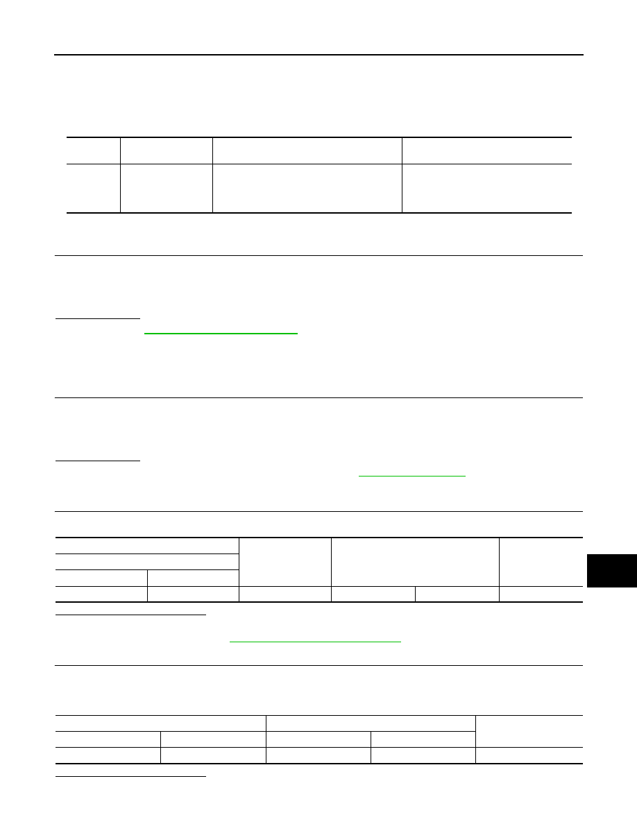
DTC No.
Trouble diagnosis
name
DTC detecting condition
Possible cause
B26F1
IGN RELAY OFF
BCM transmits the ignition relay control signal
(ON: 0 V) or ignition switch ON signal (ON)
(CAN), but does not receives ignition switch
ON signal (ON) (CAN) from IPDM E/R.
• Harness or connectors
(Ignition relay circuit is open)
• BCM
• IPDM E/R
(+)
(–)
Condition
Voltage (V)
(Approx.)
BCM
Connector
Terminal
M71
98
Ground
Ignition switch
ON
0
BCM
IPDM E/R
Continuity
Connector
Terminal
Connector
Terminal
M71
98
E17
69
Existed