Nissan Versa Note. Instruction - part 790


  Index      Nissan     Nissan Versa Note (2014 year) - Service and Repair Instruction


Search            copyright infringement  


Content   ..  788  789  790  791   ..


Nissan Versa Note. Instruction - part 790


TM-40

< UNIT DISASSEMBLY AND ASSEMBLY >

[5MT: RS5F91R]

TRANSAXLE ASSEMBLY

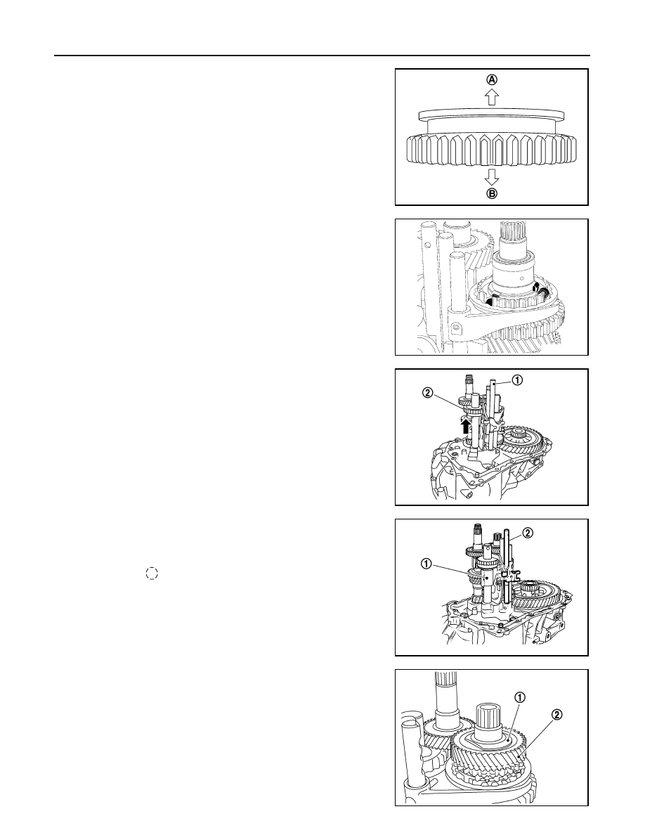
• Be careful with the orientation of 3rd-4th coupling sleeve.

• Install 3rd input gear of input shaft assembly so that it is

set under reverse main gear of 3rd-4th coupling sleeve.

• Replace 3rd-4th coupling sleeve and 3rd-4th synchronizer

hub as a set.

c.

Install springs and insert keys to 3rd-4th synchronizer hub.

d. Apply gear oil to 4th baulk ring.
e. Install 4th baulk ring.

27. Install 5th-reverse fork rod (1) to clutch housing.

CAUTION:

Replace 5th-reverse fork rod and 5th-reverse shift fork as a

set.

a. Pull gear of reverse gear (2) up.
b. Temporarily install 5th-reverse fork rod to clutch housing.

c.

Press gear of reverse gear (1) down and then install 5th-reverse

fork rod (2) to clutch housing.

CAUTION:

Set levers of 5th-reverse fork rod so as to align with reverse
gear groove ( ).

28. Install 4th main gear (2) and spacer (1) to mainshaft.

CAUTION:

Install spacer so that spacer protrusion faces rear side of

transaxle.

29. Press 3rd-4th shift fork down and then shift 3rd-4th coupling

sleeve to 3rd gear side.

(A)

: 4th main gear side

(B)

: 3rd main gear side 

PCIB1551E

MCIB0061E

PCIB1629E

PCIB1552E

PCIB1529E

TRANSAXLE ASSEMBLY

TM-41

< UNIT DISASSEMBLY AND ASSEMBLY >

[5MT: RS5F91R]

C

E

F

G

H

I

J

K

L

M

A

B

TM

N

O

P

30. Move the shifter lever A (1) to the 3rd gear position.

NOTE:

• If it is not moved to the 3rd gear position, transaxle case can-

not be installed to clutch housing.

• The 3rd gear position means that shifter lever A is fully rotated

clockwise and it is returned approximately 10 degrees.

31. Apply recommended sealant to transaxle case mating surface of

clutch housing.

CAUTION:

• Use Genuine Silicone RTV or equivalent. Refer to 

GI-22,

"Recommended Chemical Products and Sealants"

.

• Do not allow old Silicone RTV, moisture, oil, or foreign

matter to remain on mating surface.

• Check that mating surface is not damaged.

• Apply a continuous bead of Silicone RTV to the mating surface.

32. Install transaxle case to clutch housing. If it is difficult to install,

slightly rotate shifter lever A counterclockwise, and then install.

CAUTION:

• Do not damage Silicone RTV bead with transaxle case or

other objects during installation.

• Be careful to align the lever of 5th-reverse fork rod with

reverse gear groove.

33. Rotate input shaft so that bearing and shaft fit each other, and

then tighten transaxle bolts (

) to the specified torque.

34. Apply recommended sealant to position switch thread and check

ball plug thread. Install to transaxle case and tighten to specified

torque.

CAUTION:

• Use Genuine Silicone RTV or equivalent. Refer to 

GI-22,

"Recommended Chemical Products and Sealants"

.

• Do not allow old Silicone RTV, moisture, oil, or foreign

matter to remain on thread.

35. Apply gear oil to mainshaft spline.
36. Install 5th main gear (1) to mainshaft, using a suitable bolt (A)

[M10 x 1.0] and a suitable nut (B).

PCIB1524E

(1)

: Selector

(2)

: Shift fork

PCIB1553E

JPDIC0610ZZ

PCIB1554E

TM-42

< UNIT DISASSEMBLY AND ASSEMBLY >

[5MT: RS5F91R]

TRANSAXLE ASSEMBLY

37. Install adapter plate (1), bushing (2), and 5th input gear (3) to

input shaft.

CAUTION:

Be careful with the orientation of adapter plate.

38. Install 5th-reverse synchronizer hub, 5th-reverse coupling sleeve, and 5th-reverse shift fork.
a. Apply gear oil to 5th-reverse baulk ring.
b. Install 5th-reverse baulk ring (1) to 5th input gear.

CAUTION:

Be careful with the orientation of 5th-reverse baulk ring.

c.

Install synchronizer levers (2) to 5th-reverse synchronizer hub

(3).

CAUTION:

• Replace 5th-reverse synchronizer hub and 5th-reverse

coupling sleeve as a set.

• Be careful with the orientation of synchronizer lever.

d. Install 5th-reverse synchronizer hub assembly and lock washer to input shaft.

CAUTION:

• Be careful with the orientation of 5th-reverse synchro-

nizer hub.

• Do not allow synchronizer lever (1) to overlap 5th-reverse

baulk ring protrusion (A).

: Transaxle case side

PCIB1555E

: 5th-reverse synchronizer hub side

: 5th input gear side

JPDIC0421ZZ

PCIB1556E

(2)

: 5th-reverse baulk ring

(3)

: 5th-reverse synchronizer hub

JPDIC0408ZZ

TRANSAXLE ASSEMBLY

TM-43

< UNIT DISASSEMBLY AND ASSEMBLY >

[5MT: RS5F91R]

C

E

F

G

H

I

J

K

L

M

A

B

TM

N

O

P

e. Set 5th-reverse shift fork (1) to 5th-reverse coupling sleeve, and

then install them to 5th-reverse fork rod and input shaft.

CAUTION:

Do not reuse nut.

CAUTION:

• Be careful with the orientation of 5th-reverse coupling

sleeve.

• Replace 5th-reverse synchronizer hub and 5th-reverse

coupling sleeve as a set.

• Replace 5th-reverse shift fork and 5th-reverse fork rod as

a set.

f.

Check that the shifter lever A is in the 3rd position. Press 5th-

reverse shift fork (1) and move shifter lever A to 5th gear.

g. Tighten bolt (B) to the specified torque.
h. Tighten nut (C) to the specified torque.

CAUTION:

Do not reuse nut.

i.

Install retaining pin to 5th-reverse shift fork, using suitable tool.

CAUTION:

Do not reuse retaining pin.

39. Move shifter lever A (1) to the neutral position.
40. Install O-ring to rear housing.

CAUTION:

Do not reuse O-ring.

(A)

: Suitable tool

(B)

: Bolt

(C)

: Nut

JPDIC0532ZZ

: 5th input gear side

JPDIC0409ZZ

(A)

: Suitable tool

JPDIC0532ZZ

SCIA7130E


Content   ..  788  789  790  791   ..