Nissan Versa Note. Instruction - part 403


  Index      Nissan     Nissan Versa Note (2014 year) - Service and Repair Instruction


Search            copyright infringement  


Content   ..  401  402  403  404   ..


Nissan Versa Note. Instruction - part 403


PREPARATION

EX-3

< PREPARATION >

C

D

E

F

G

H

I

J

K

L

M

A

EX

N

P

O

PREPARATION

PREPARATION

Special Service Tool

INFOID:0000000009405627

The actual shapes of Kent-Moore tools may differ from those of special service tools illustrated here.

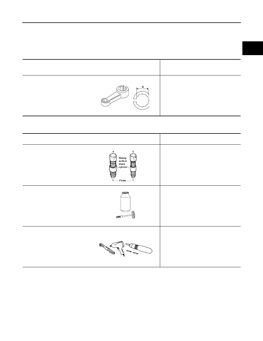
Commercial Service Tool

INFOID:0000000009405628

Tool number
(Kent-Moore No.)
Tool name

 Description

KV10114400
(J-38365-N1)
Heated oxygen sensor wrench

Loosening or tightening heated oxygen sen-
sors:
a: 22 mm (0.87 in)

S-NT636

(Kent-Moore No.)
Tool name

Description

(J-43897-18)
(J-43897-12)
Oxygen sensor thread cleaner

Reconditioning the exhaust system threads 
before installing a new oxygen sensor (Use 
with anti-seize lubricant shown below):
a: J-43897-18 (18 mm dia.) for zirconia ox-
ygen sensor
b: J-43897-12 (12 mm dia.) for titania oxy-
gen sensor

Anti-seize lubricant (Permatex 133AR 
or equivalent meeting MIL specifica-
tion MIL-A-907)

Lubricating oxygen sensor thread cleaning 
tool when reconditioning exhaust system 
threads

Power tool

Loosening nuts, screws and bolts

AEM488

AEM489

PIIB1407E

EX-4

< PERIODIC MAINTENANCE >

EXHAUST SYSTEM

PERIODIC MAINTENANCE

EXHAUST SYSTEM

Inspection

INFOID:0000000009405629

Check exhaust pipes, muffler, and mounting for improper attach-

ment, leaks, cracks, damage or deterioration.

• If anything is found, repair or replace damaged parts.

SMA211A

EXHAUST SYSTEM

EX-5

< REMOVAL AND INSTALLATION >

C

D

E

F

G

H

I

J

K

L

M

A

EX

N

P

O

REMOVAL AND INSTALLATION

EXHAUST SYSTEM

Exploded View

INFOID:0000000008969011

WARNING:

• Perform the procedures with the exhaust system fully cooled down to avoid injury from the hot

exhaust system. 

• Be careful not to cut your hand on the insulator edge.

CAUTION:

Use genuine NISSAN exhaust system parts or equivalent, which are specifically designed for heat

resistance, corrosion resistance, and shape.

REMOVAL

• Disconnect each joint and mounting.

• Remove heated oxygen sensor 2 (1) using Tool (A).

1.

Seal bearing

2.

Spring

3.

Heated oxygen sensor 2

4.

Front Exhaust tube

5.

Seal bearing

6.

Mounting rubber

7.

Center muffler

8.

Ring gasket

9.

Main muffler

A.

To Exhaust manifold

ALBIA1144ZZ

Tool number

: KV10114400 (J-38365-N1)

: Front

ALBIA1136ZZ

EX-6

< REMOVAL AND INSTALLATION >

EXHAUST SYSTEM

INSTALLATION

CAUTION:

• Do not reuse gasket.

• Do not reuse seal bearing.

• Discard any heated oxygen sensor 2 which has been dropped from a height of more than 0.5 m (19.7

in) onto a hard surface such as a concrete floor. Use a new one. 

• Before installing a new heated oxygen sensor 2, clean exhaust system threads using a suitable tool

and apply anti-seize lubricant.

• Do not over tighten heated oxygen sensor 2. Doing so may cause damage to the heated oxygen sen-

sor 2, resulting in the “MIL” coming on. 

• Prevent rust preventives from adhering to the sensor body.

• If heat insulator is badly deformed, repair or replace it. If deposits such as mud pile up on the heat

insulator, remove them.

• When installing heat insulator avoid large gaps or interference between heat insulator and each

exhaust pipe.

• Remove deposits from the sealing surface of each connection. Connect them securely to avoid

exhaust gas leaks. 

• When installing each mounting rubber, use silicon oil to avoid twisting.

• Temporarily tighten nuts and bolts. Check each part for unusual interference and mounting rubber

interference, and then tighten them to the specified torque. 

• When installing each mounting rubber, avoid twisting or unusual extension in up/down, front/rear

and right/left directions.

Exhaust Manifold to Exhaust Front Tube

1. Place a piece of wood (A) on seal bearing (2) and securely

insert the seal bearing on the exhaust manifold (1) side, using a

plastic hammer (B).

CAUTION:

• Do not damage the seal bearing surface during insertion.

• If seal bearing is inserted by hammering directly without

using a piece of wood, the seal bearing is deformed and

exhaust gas leaks. To insert seal bearing, always use a

piece of wood and insert straight.

2. Check that seal bearing (1) is in absolute contact (C) with the

flange (A). If there is clearance (B), insert seal bearing straight

by hand to bring the seal bearing into absolute contact with the

flange.

CAUTION:

• Do not use a tool for insertion.

• Do not insert seal bearing by tightening exhaust front

tube.

Oxygen sensor thread cleaner

: J-43897-12

Oxygen sensor thread cleaner

: J-43897-18

JPBIA6288ZZ

JPBIA6289ZZ


Content   ..  401  402  403  404   ..