Nissan Versa Note. Instruction - part 385


  Index      Nissan     Nissan Versa Note (2014 year) - Service and Repair Instruction


Search            copyright infringement  


Content   ..  383  384  385  386   ..


Nissan Versa Note. Instruction - part 385


EM-56

< REMOVAL AND INSTALLATION >

[HR16DE]

TIMING CHAIN

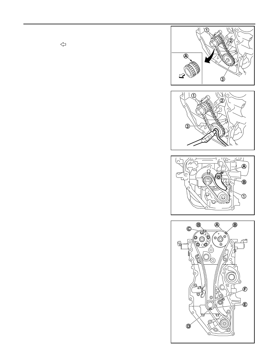
a. Install the crankshaft sprocket (1), the oil pump drive chain (2),

and the oil pump sprocket (3) at the same time.

• Install the crankshaft sprocket so that its invalid gear area (A)

is toward the back of the engine.

• Install the oil pump sprocket so that its protrusion faces the

front of engine.

NOTE:

There is no matching mark in the oil pump drive related parts. 

b. Hold the top of the oil pump shaft using the socket (size: E8),

and then tighten the oil pump sprocket nut.

c.

Install oil pump drive chain tensioner (1).

• Insert the body into the shaft (B) while inserting the spring into

the attaching hole (A) of cylinder block front surface.

• Check that the tension is applied to the oil pump drive chain

after installing.

2. Install timing chain:

• Install by aligning matching marks on each sprocket and tim-

ing chain.

• If these matching marks are not aligned, rotate the camshaft

slightly to correct the position.

CAUTION:

• After the matching marks are aligned, keep them aligned

by holding them. 

• To avoid skipped teeth, do not rotate crankshaft and cam-

shaft until front cover is installed.

: Engine front

JPBIA5248ZZ

(1) : Crankshaft sprocket
(2) : Oil pump drive chain 
(3) : Oil pump sprocket

JPBIA4230ZZ

JPBIA4143ZZ

(A) : Matching mark (Peripheral groove)
(B) : Pink link
(C) : Matching mark (Peripheral groove)
(D) : Orange link
(E) : Matching mark (stamp)
(F) : Crankshaft key (point straight up)

JPBIA4144ZZ

TIMING CHAIN

EM-57

< REMOVAL AND INSTALLATION >

[HR16DE]

C

D

E

F

G

H

I

J

K

L

M

A

EM

N

P

O

3. Install timing chain tension guide (2) and timing chain slack

guide (1).

4. Install chain tensioner (1).

• Secure the plunger at the most compressed position using a

stopper pin (A), and then install it.

• Pull out the stopper pin after installing the chain tensioner.

5. Check matching mark position of timing chain and each sprocket again.
6. Install the front oil seal to the front cover. Refer to 

EM-74, "FRONT OIL SEAL : Removal and Installation"

.

7. Install front cover with the following procedure:
a. Apply a continuous bead of liquid gasket to the engine block joint locations (A) as shown. 

Use Genuine Silicone RTV Sealant or equivalent. Refer to 

GI-22, "Recommended Chemical Products

and Sealants"

CAUTION:

• Do not confirm torque after the 5 minutes have elapsed.

• Do not confirm torque after the 5 minutes have elapsed.

• Then allow 30 minutes for the liquid gasket to set before

adding oil to the engine.

b. Apply a continuous bead of liquid gasket to front cover as shown using suitable tool.

JPBIA4141ZZ

PBIC3722E

(1) : Cylinder head
(2) : Cylinder block
(3) : Oil pan (upper)
(A) : Liquid gasket application area [3.0 - 4.0 mm (0.12 - 0.16 in) diam-

eter]

JPBIA4145ZZ

EM-58

< REMOVAL AND INSTALLATION >

[HR16DE]

TIMING CHAIN

Use Genuine Silicone RTV Sealant or equivalent. Refer to 

GI-22, "Recommended Chemical Products

and Sealants"

.

CAUTION:

• Do not confirm torque after the 5 minutes have elapsed.

• Do not confirm torque after the 5 minutes have elapsed.

• Then allow 30 minutes for the liquid gasket to set before

adding oil to the engine.

c.

Tighten bolts in the numerical order as shown.

NOTE:

Refer to the following for the installation position of bolts.

d. After all bolts are tightened, retighten them to specified torque in

numerical order as shown.

CAUTION:

Be sure to wipe off any excessive liquid gasket leaking to

surface.

8. Insert crankshaft pulley by aligning with crankshaft key. 

• When inserting crankshaft pulley with a plastic hammer, tap on its center portion (not circumference).

(1) : Front cover edge
(A) : Liquid gasket application area
(b) : 4.0 - 5.6 mm

(c)

: Liquid gasket application area [3.0 - 4.0 mm (0.12 - 0.16 in) diame-
ter]

JPBIA4146ZZ

M6 bolt

: No. 1

6.6 N·m (0.67 kg-m, 
58 in-lb)

M10 bolts

: No. 11, 12, 13

55.0 N·m (5.6 kg-m, 
41 ft-lb)

M10 bolts

: No. 14, 15

55.0 N·m (5.6 kg-m, 
41 ft-lb)

M8 bolts

: Except above 25.0 N·m (2.6 kg-m, 

18 ft-lb)

JPBIA4139ZZ

TIMING CHAIN

EM-59

< REMOVAL AND INSTALLATION >

[HR16DE]

C

D

E

F

G

H

I

J

K

L

M

A

EM

N

P

O

CAUTION:

Do not damage front oil seal lip section.

9. Tighten crankshaft pulley bolt:

• Secure crankshaft pulley with a suitable tool and tighten crankshaft pulley bolt.

a. Apply new engine oil to thread and seat surfaces of crankshaft pulley bolt.
b. Tighten crankshaft pulley bolt.

c. Put a paint mark (B) on crankshaft pulley, mating with any one of

six easy to recognize angle marks (A) on crankshaft bolt flange

(1). 

d. Turn another 60 degrees clockwise (angle tightening).

• Check the tightening angle with movement of one angle mark.

10. Check that crankshaft turns smoothly by rotating by hand clockwise using suitable tool.
11. Installation of the remaining components is in the reverse order of removal.

INSPECTION AFTER INSTALLATION

• Before starting engine, check oil/fluid levels, including engine coolant and engine oil. If less than required

quantity, fill to the specified level. Refer to 

MA-11, "Fluids and Lubricants"

.

• Use procedure below to check for fuel leaks.

• Turn ignition switch ON (with engine stopped). With fuel pressure applied to fuel piping, check for fuel leaks

at connection points.

• Start engine. With engine speed increased, check again for fuel leaks at connection points.

• Run engine to check for unusual noise and vibration.

NOTE:

If hydraulic pressure inside timing chain tensioner drops after removal and installation, slack in the guide

may generate a pounding noise during and just after engine start. However, this is normal. Noise will stop

after hydraulic pressure rises.

• Warm up engine thoroughly to make sure there are no leaks of fuel, exhaust gas, or any oils/fluids including

engine oil and engine coolant.

• Bleed air from passages in lines and hoses, such as in cooling system.

• After cooling down engine, again check oil/fluid levels including engine oil and engine coolant. Refill to spec-

ified level, if necessary.

• Summary of the inspection items:

*Power steering fluid, brake fluid, etc.

Crankshaft pulley bolt : 35.0 N·m (3.6 kg-m, 26 ft-lb)

PBIC3726E

Item

Before starting engine

Engine running

After engine stopped

Engine coolant

Level

Leaks

Level

Engine oil

Level

Leaks

Level

Transmission/
transaxle fluid 

CVT Models

Leaks

Level/Leaks

Leaks

M/T Models

Level/Leaks

Leaks

Level/Leaks

Other oils and fluids*

Level

Leaks

Level

Fuel

Leaks

Leaks

Leaks

Exhaust gas

Leaks


Content   ..  383  384  385  386   ..