Nissan Versa Note. Instruction - part 309
EC-218
< DTC/CIRCUIT DIAGNOSIS >
[HR16DE]
P0132 A/F SENSOR 1
Diagnosis Procedure
INFOID:0000000009020734
1.
CHECK GROUND CONNECTION
1. Turn ignition switch OFF.
2. Check ground connection E15. Refer to Ground Inspection in
.
Is the inspection result normal?
YES
>> GO TO 2.
NO
>> Repair or replace ground connection.
2.
CHECK AIR FUEL RATIO (A/F) SENSOR 1 POWER SUPPLY CIRCUIT
1. Disconnect A/F sensor 1 harness connector.
2. Turn ignition switch ON.
3. Check the voltage between A/F sensor 1 harness connector and ground.
Is the inspection result normal?
YES
>> GO TO 4.
NO
>> GO TO 3.
3.
DETECT MALFUNCTIONING PART
Check the following.
• IPDM E/R harness connector F42
• 20A fuse (No. 53)
• Harness for open or short between A/F sensor 1 and fuse
>> Repair or replace harness or connectors.
4.
CHECK A/F SENSOR 1 INPUT SIGNAL CIRCUIT FOR OPEN AND SHORT
1. Turn ignition switch OFF.
2. Disconnect ECM harness connector.
3. Check the continuity between A/F sensor 1 harness connector and ECM harness connector.
4. Check the continuity between A/F sensor 1 harness connector and ground or ECM harness connector
and ground.
5. Also check harness for short to power.
Is the inspection result normal?
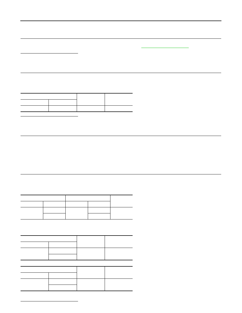
A/F sensor 1
Ground
Voltage
Connector
Terminal
F12
4
Ground
Battery voltage
A/F sensor 1
ECM
Continuity
Connector
Terminal
Connector
Terminal
F12
1
F11
49
Existed
2
53
A/F sensor 1
Ground
Continuity
Connector
Terminal
F12
1
Ground
Not existed
2
ECM
Ground
Continuity
Connector
Terminal
F11
49
Ground
Not existed
53