Nissan Versa Note. Instruction - part 112
BRC-12
< SYSTEM DESCRIPTION >
[VDC/TCS/ABS]
SYSTEM
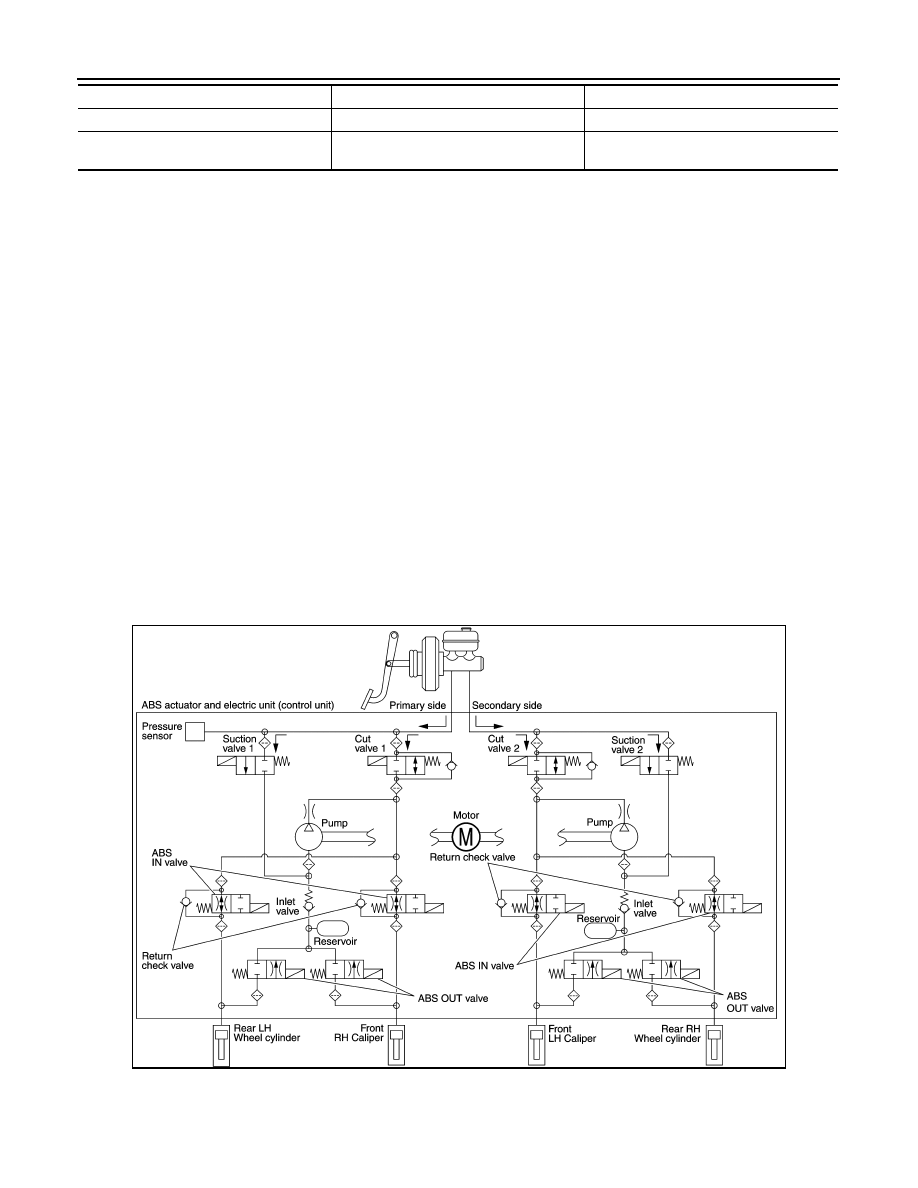
Front RH brake caliper
• Brake fluid is conveyed to the pump from the master cylinder through suction valve 1 and is pressurized by
the pump operation. The pressurized brake fluid is supplied to the front RH brake caliper through the ABS IN
valve. For the left caliper, brake fluid pressure is maintained because the pressurization is unnecessary. The
pressurization for the left caliper is controlled separately from the right caliper.
Front LH brake caliper
• Brake fluid is conveyed to the pump from the master cylinder through suction valve 2 and is pressurized by
the pump operation. The pressurized brake fluid is supplied to the front LH brake caliper through the ABS IN
valve. For the right caliper, brake fluid pressure is maintained because the pressurization is unnecessary.
The pressurization for the right caliper is controlled separately from the left caliper.
Rear RH wheel cylinder
• Brake fluid is conveyed to the pump from the master cylinder through suction valve 2 and is pressurized by
the pump operation. The pressurized brake fluid is supplied to the rear RH wheel cylinder through the ABS
IN valve. For the left wheel cylinder, brake fluid pressure is maintained because the pressurization is unnec-
essary. The pressurization for the left wheel cylinder is controlled separately from the right wheel cylinder.
Rear LH wheel cylinder
• Brake fluid is conveyed to the pump from the master cylinder through suction valve 1 and is pressurized by
the pump operation. The pressurized brake fluid is supplied to the rear LH wheel cylinder through the ABS
IN valve. For the right wheel cylinder, brake fluid pressure is maintained because the pressurization is
unnecessary. The pressurization for the right wheel cylinder is controlled separately from the left wheel cylin-
der.
VDC and TCS Functions Start Operating (Pressure Holds)
ABS OUT valve
Power supply is not supplied (close)
Power supply is not supplied (close)
Each brake caliper and each wheel cylinder
(fluid pressure)
—
Pressure increases
Name
Not activated
Pressure increases
JSFIA0677GB