Nissan Versa Sedan. Instruction - part 917


  Index      Nissan     Nissan Versa Sedan (2014 year) - Service and Repair Instruction


Search            copyright infringement  


Content   ..  915  916  917  918   ..


Nissan Versa Sedan. Instruction - part 917


WW-18

< SYSTEM DESCRIPTION >

DIAGNOSIS SYSTEM (IPDM E/R) (WITHOUT INTELLIGENT KEY SYSTEM)

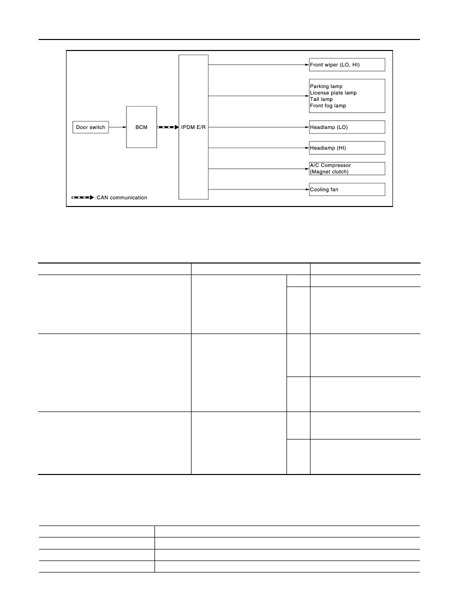
Concept of Auto Active Test

• IPDM E/R starts the auto active test with the door switch signals transmitted by BCM via CAN communica-

tion. Therefore, the CAN communication line between IPDM E/R and BCM is considered normal if the auto

active test starts successfully.

• The auto active test facilitates troubleshooting if any systems controlled by IPDM E/R cannot be operated.

Diagnosis Chart in Auto Active Test

CONSULT Function (IPDM E/R)

INFOID:0000000009543751

APPLICATION ITEM

CONSULT performs the following functions via CAN communication with IPDM E/R.

JMMIA0812GB

Symptom

Inspection contents

Possible cause

Any of the following components do not operate

• Parking  lamp
• License plate lamp
• Tail  lamp
• Front fog lamp
• Headlamp (HI, LO)
• Front wiper (HI, LO)

Perform auto active test.
Does the applicable system op-
erate?

YES

BCM signal input circuit

NO

• Lamp or motor
• Lamp or motor ground circuit
• Harness or connector between 

IPDM E/R and applicable system

• IPDM E/R

A/C compressor does not operate

Perform auto active test.
Does the magnet clutch oper-
ate?

YES

• BCM signal input circuit
• CAN communication signal be-

tween BCM and ECM

• CAN communication signal be-

tween ECM and IPDM E/R

NO

• Magnet clutch
• Harness or connector between 

IPDM E/R and magnet clutch

• IPDM E/R

Cooling fan does not operate

Perform auto active test.
Does the cooling fan operate?

YES

• ECM signal input circuit
• CAN communication signal be-

tween ECM and IPDM E/R

NO

• Cooling fan motor
• Harness or connector between 

IPDM E/R and cooling fan motor

• IPDM E/R

Direct Diagnostic Mode

Description

Ecu Identification

The IPDM E/R part number is displayed.

Self Diagnostic Result

The IPDM E/R self diagnostic results are displayed.

Data Monitor

The IPDM E/R input/output data is displayed in real time.

DIAGNOSIS SYSTEM (IPDM E/R) (WITHOUT INTELLIGENT KEY SYSTEM)

WW-19

< SYSTEM DESCRIPTION >

C

D

E

F

G

H

I

J

K

M

A

B

WW

N

O

P

ECU IDENTIFICATION

The IPDM E/R part number is displayed.

SELF DIAGNOSTIC RESULT

Refer to 

PCS-46, "DTC Index"

.

DATA MONITOR

ACTIVE TEST

CAN DIAG SUPPORT MNTR

Active Test

The IPDM E/R activates outputs to test components.

CAN Diag Support Mntr

The result of transmit/receive diagnosis of CAN communication is displayed.

Direct Diagnostic Mode

Description

Monitor Item [Unit]

Main

Signals

Description

MOTOR FAN REQ [%]

×

Indicates cooling fan speed signal received from ECM on CAN communication 
line

AC COMP REQ [On/Off]

×

Indicates A/C compressor request signal received from ECM on CAN commu-
nication line

TAIL&CLR REQ [On/Off]

×

Indicates position light request signal received from BCM on CAN communica-
tion line

HL LO REQ [On/Off]

×

Indicates low beam request signal received from BCM on CAN communication 
line

HL HI REQ [On/Off]

×

Indicates high beam request signal received from BCM on CAN communication 
line

FR FOG REQ [On/Off]

×

Indicates front fog light request signal received from BCM on CAN communica-
tion line

FR WIP REQ [Stop/1LOW/Low/Hi]

×

Indicates front wiper request signal received from BCM on CAN communication 
line

WIP AUTO STOP [STOP P/ACT P]

×

Indicates condition of front wiper auto stop signal

WIP PROT [Off/BLOCK]

×

Indicates condition of front wiper fail-safe operation

IGN RLY1 -REQ [On/Off]

Indicates ignition switch ON signal received from BCM on CAN communication 
line

IGN RLY [On/Off]

×

Indicates condition of ignition relay

INTER/NP SW [On/Off]

Indicates condition of CVT shift position

ST RLY CONT [On/Off]

Indicates starter relay status signal received from BCM on CAN communication 
line

IHBT RLY -REQ [On/Off]

Indicates starter control relay signal received from BCM on CAN communication 
line

ST/INHI RLY [Off/ ST /INHI]

Indicates condition of starter relay and starter control relay

DETENT SW [On/Off]

Indicates condition of CVT shift selector (park position switch)

DTRL REQ [Off]

Indicates daytime light request signal received from BCM on CAN communica-
tion line

THFT HRN REQ [On/Off]

Indicates theft warning horn request signal received from BCM on CAN commu-
nication line

HORN CHIRP [On/Off]

Indicates horn reminder signal received from BCM on CAN communication line

Test item

Description

HORN

This test is able to check horn operation [On].

FRONT WIPER

This test is able to check wiper motor operation [Hi/Lo/Off].

MOTOR FAN

This test is able to check cooling fan operation [4/3/2/1].

EXTERNAL LAMPS

This test is able to check external lamp operation [Fog/Hi/Lo/TAIL/Off].

WW-20

< SYSTEM DESCRIPTION >

DIAGNOSIS SYSTEM (IPDM E/R) (WITHOUT INTELLIGENT KEY SYSTEM)

Refer to 

LAN-12, "CAN Diagnostic Support Monitor"

.

BCM, IPDM E/R

WW-21

< ECU DIAGNOSIS INFORMATION >

C

D

E

F

G

H

I

J

K

M

A

B

WW

N

O

P

ECU DIAGNOSIS INFORMATION

BCM, IPDM E/R

List of ECU Reference

INFOID:0000000009269557

ECU

Reference

BCM (with Intelligent Key system)

BCS-28, "Reference Value"

BCS-45, "Fail-safe"

BCS-47, "DTC Inspection Priority Chart"

BCS-48, "DTC Index"

BCM (without Intelligent Key system) 

BCS-93, "Reference Value"

BCS-104, "Fail-safe"

BCS-104, "DTC Inspection Priority Chart"

BCS-105, "DTC Index"

IPDM E/R (with Intelligent Key system)

PCS-13, "Reference Value"

PCS-18, "Fail-safe"

PCS-19, "DTC Index"

IPDM E/R (without Intelligent Key system) 

PCS-40, "Reference Value"

PCS-44, "Fail-Safe"

PCS-46, "DTC Index"


Content   ..  915  916  917  918   ..