Nissan Versa Sedan. Instruction - part 912


  Index      Nissan     Nissan Versa Sedan (2014 year) - Service and Repair Instruction


Search            copyright infringement  


Content   ..  910  911  912  913   ..


Nissan Versa Sedan. Instruction - part 912


TRANSMITTER

WT-43

< REMOVAL AND INSTALLATION >

C

D

F

G

H

I

J

K

L

M

A

B

WT

N

O

P

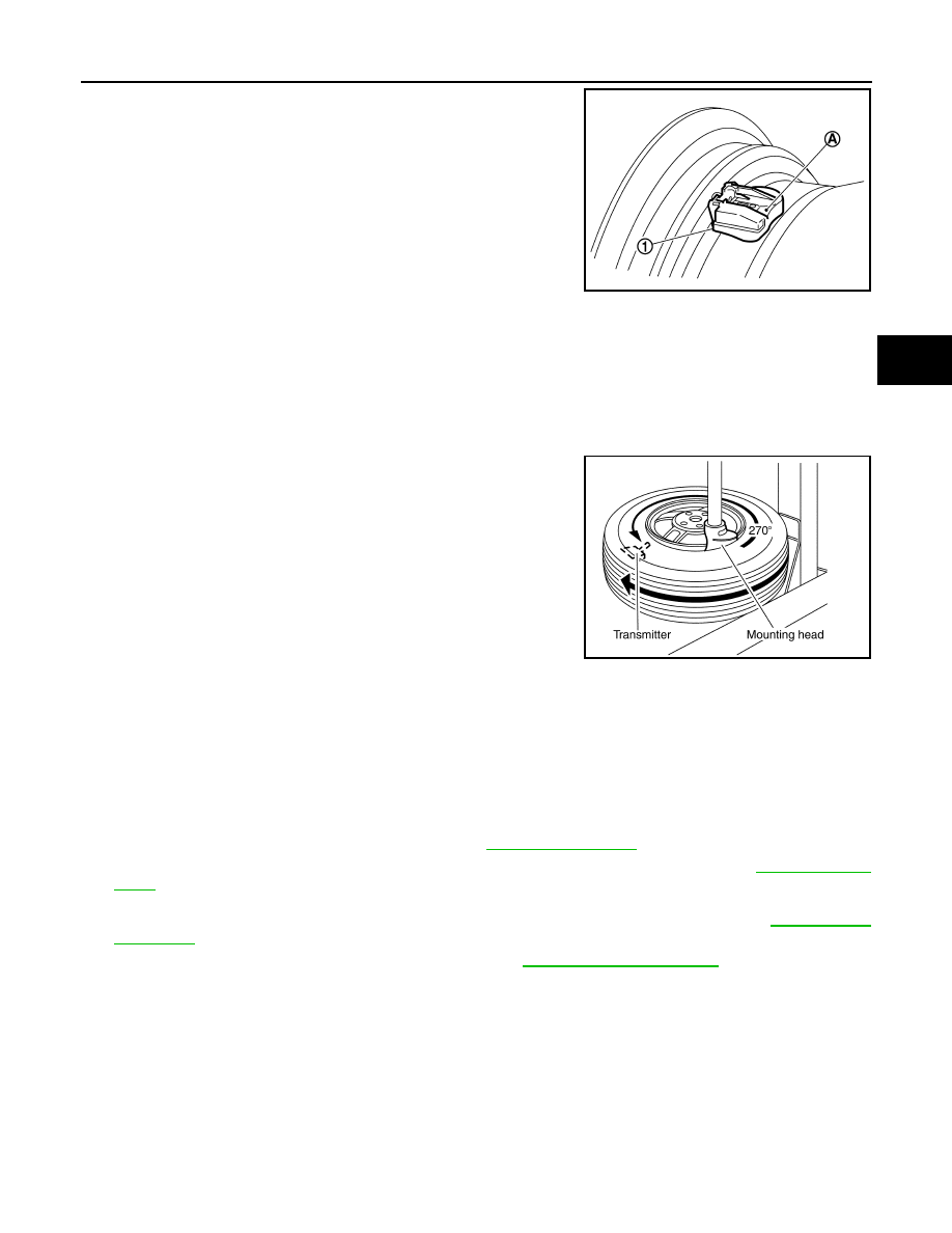
5. Install transmitter (1) to road wheel while pressing at position

(A).

CAUTION:

• Check that O-ring contacts horizontally with road wheel.

• Check that the base of the valve stem is positioned in the

groove of the metal plate.

6. Install and tighten the valve stem nut to the specified torque.

CAUTION:

Do not use power tool for installation.

7. Place wheel on turntable of tire machine. Ensure that transmitter

is 270 degrees from mounting/dismounting head.

NOTE:

Do not touch transmitter with mounting head.

8. Apply a suitable non-silicone lubricant to the tire outside bead.

CAUTION:

• Do not use silicone lubricant. Use of silicone lubricant will

deteriorate the tire and wheel.

• Do not allow lubricant to make contact with transmitter.

9. Install the tire outside bead onto the road wheel as normal.

NOTE:

If the tire is being reused, align the matching mark applied on

the tire with the position of the road wheel valve stem assembly for the purpose of road wheel and tire bal-

ance adjustment after installation. Ensure that the tire does not rotate relative to road wheel.

10. Install the valve core and inflate tire.

CAUTION:

Do not reuse valve core.

11. Install the valve cap.

CAUTION:

Do not reuse valve cap.

12. Balance the road wheel and tire assembly. Refer to 

WT-39, "Adjustment"

.

13. Install road wheel and tire assembly in appropriate wheel position on vehicle. Refer to 

WT-39, "Adjust-

ment"

.

NOTE:

If replacing the transmitter, then transmitter wake up operation must be performed. Refer to 

WT-19, "Work

Procedure"

.

14. Adjust neutral position of steering angle sensor. Refer to 

BRC-55, "Work Procedure"

.

JSEIA0377ZZ

Valve stem nut 
tightening torque

: 7.7 N·m (0.79 kg-m, 68 in-lb)

WEIA0046E

WT-44

< REMOVAL AND INSTALLATION >

TIRE PRESSURE RECEIVER

TIRE PRESSURE RECEIVER

Removal and Installation

INFOID:0000000009267481

The tire pressure receiver is integral to the remote keyless entry receiver. Refer to 

DLK-188, "Removal and

Installation"

(WITH INTELLIGENT KEY SYSTEM) or 

DLK-318, "Removal and Installation"

 (WITHOUT INTEL-

LIGENT KEY SYSTEM).

SERVICE DATA AND SPECIFICATIONS (SDS)

WT-45

< SERVICE DATA AND SPECIFICATIONS (SDS) 

C

D

F

G

H

I

J

K

L

M

A

B

WT

N

O

P

SERVICE DATA AND SPECIFICATIONS (SDS)

SERVICE DATA AND SPECIFICATIONS (SDS)

Road Wheel

INFOID:0000000009267482

ALUMINUM WHEEL 

STEEL WHEEL

Tire Air Pressure

INFOID:0000000009267483

Unit: kPa (kg/cm

2

, psi)

Item

Limit

Radial runout

Lateral deflection

Less than 0.3 mm (0.012 in)

Vertical deflection

Allowable imbalance

Dynamic (At flange)

Less than 5 g (0.17 oz) (one side)

Static (At flange)

Less than 10 g (0.35 oz)

Item

Limit

Radial runout

Lateral deflection

Less than 0.8 mm (0.031 in)

Vertical deflection

Less than 0.5 mm (0.020 in)

Allowable imbalance

Dynamic (At flange)

Less than 5 g (0.17 oz) (one side)

Static (At flange)

Less than 10 g (0.35 oz)

Tire size

Transmission

Cold tire pressure

Front

Rear

Spare

P185/65R15 86H

M/T or A/T

230 (2.3, 33)

230 (2.3, 33)

P185/65R15 86H

CVT

250 (2.5, 36)

250 (2.5, 36)

P195/55R16 86V

CVT

250 (2.5, 36)

250 (2.5, 36)

T125/70D15 95M

All

420 (4.2, 60)

WW-1

DRIVER CONTROLS

C

D

E

F

G

H

I

J

K

M

SECTION 

WW

A

B

WW

N

O

P

CONTENTS

WIPER & WASHER

PRECAUTION ...............................................

3

PRECAUTIONS ...................................................

3

Precaution for Supplemental Restraint System 
(SRS) "AIR BAG" and "SEAT BELT PRE-TEN-
SIONER" .................................................................
..

3

Precaution for Procedure without Cowl Top Cover ......

3

PREPARATION ............................................

4

PREPARATION ...................................................

4

Commercial Service Tool  ..........................................

4

SYSTEM DESCRIPTION  ..............................

5

COMPONENT PARTS  ........................................

5

Component Parts Location ........................................

5

Component Description ............................................

5

SYSTEM ..............................................................

6

System Diagram ........................................................

6

System Description  ...................................................

6

Fail-Safe ....................................................................

8

DIAGNOSIS SYSTEM (BCM) (WITH INTELLI-
GENT KEY SYSTEM) ..........................................

9

COMMON ITEM ...........................................................

9

COMMON ITEM : CONSULT Function (BCM - 
COMMON ITEM) .....................................................
..

9

WIPER .......................................................................

10

WIPER : CONSULT Function (BCM - WIPER)  .......

10

DIAGNOSIS SYSTEM (BCM) (WITHOUT IN-
TELLIGENT KEY SYSTEM) ...............................

11

COMMON ITEM .........................................................

11

COMMON ITEM : CONSULT Function (BCM - 
COMMON ITEM) .....................................................

11

WIPER .......................................................................

12

WIPER : CONSULT Function (BCM - WIPER)  .......

12

DIAGNOSIS SYSTEM (IPDM E/R) (WITH IN-
TELLIGENT KEY SYSTEM)  .............................

13

Diagnosis Description ..............................................

13

CONSULT Function (IPDM E/R)  .............................

14

DIAGNOSIS SYSTEM (IPDM E/R) (WITHOUT 
INTELLIGENT KEY SYSTEM) ..........................

17

Diagnosis Description ..............................................

17

CONSULT Function (IPDM E/R)  .............................

18

ECU DIAGNOSIS INFORMATION ..............

21

BCM, IPDM E/R .................................................

21

List of ECU Reference .............................................

21

WIRING DIAGRAM ......................................

22

FRONT WIPER AND WASHER SYSTEM  ........

22

Wiring Diagram ........................................................

22

BASIC INSPECTION  ...................................

27

DIAGNOSIS AND REPAIR WORKFLOW  ........

27

Work Flow ................................................................

27

DTC/CIRCUIT DIAGNOSIS  .........................

29

WIPER AND WASHER FUSE ...........................

29

Description ...............................................................

29

Diagnosis Procedure  ...............................................

29

FRONT WIPER MOTOR LO CIRCUIT ..............

30

Component Function Check  ....................................

30

Diagnosis Procedure  ...............................................

30

FRONT WIPER MOTOR HI CIRCUIT  ...............

32

Component Function Check  ....................................

32

Diagnosis Procedure  ...............................................

32

FRONT WIPER AUTO STOP SIGNAL CIR-
CUIT ..................................................................

34

Component Function Check  ....................................

34

Diagnosis Procedure  ...............................................

34


Content   ..  910  911  912  913   ..