Nissan Versa Sedan. Instruction - part 847


  Index      Nissan     Nissan Versa Sedan (2014 year) - Service and Repair Instruction


Search            copyright infringement  


Content   ..  845  846  847  848   ..


Nissan Versa Sedan. Instruction - part 847


TM-294

< SYSTEM DESCRIPTION >

[CVT: RE0F11A]

DIAGNOSIS SYSTEM (TCM)

SELF DIAGNOSTIC RESULTS

Refer to 

TM-311, "DTC Index"

.

DTC at 1st trip and method to read DTC

• DTC (P0705, P0711, P0720, etc.) is specified by SAE J2012/ISO 15031-6. 

• DTC and DTC at 1st trip are displayed on “Self Diagnostic results” of CONSULT.

When DTC is currently detected, “CRNT” is displayed. If “PAST” is displayed, it shows a malfunction

occurred in the past.The trip number of drive without malfunction of concerned DTC can be confirmed with

“IGN counter” inside “FFD”.

• When the DTC at the 1st trip is detected, the “timing” is displayed as “1t”. 

DTC deletion method 

NOTE:

• If the battery terminal is disconnected, the TCM memory is erased. (The disconnection time varies from sev-

eral seconds to several hours.

• If the ignition switch is left ON after repair, turn OFF the ignition switch and wait for 10 seconds or more.

Then, turn the ignition ON again. (Engine stop)

1. Touch “TRANSMISSION” of CONSULT. 

2. Touch “Self Diagnostic Result”. 

3. Touch “Erase”. (DTC memorized in TCM is erased.) 

IGN counter

The ignition counter is displayed in “FFD” and the number of times of satisfied “Driving condition A” is dis-

played after normal recovery of DTC. Refer to 

EC-52, "DIAGNOSIS DESCRIPTION : Counter System"

.

• If malfunction (DTC) is currently detected, “0” is displayed. 

• After normal recovery, every time “Driving condition A” is satisfied, the display value increases from 1 

→ 2 →

3...38 

→ 39. 

• When MIL turns OFF due to the malfunction and the counter reaches 40, the DTC is erased. 

NOTE:

The counter display of “40” cannot be checked. 

DATA MONITOR

NOTE:

The following table includes information (items) inapplicable to this vehicle. For information (items) applicable

to this vehicle, refer to CONSULT display items.

×: Application 

: Optional selection

CAN Diagnosis Support Mon-
itor

It monitors the status of CAN communication.

ECU Identification

Display the ECU identification number (part number etc.) of the selected system.

CALIB DATA

The calibration data status of TCM can be checked.
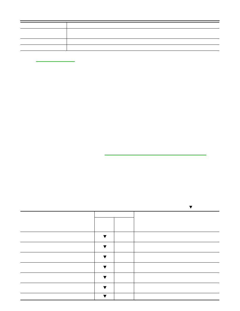
Conditions

Function

Monitored item

(Unit)

Monitor item selection

Remarks

MAIN SIG-

NALS

ECU IN-

PUT SIG-

NALS 

VSP SENSOR

(km/h or mph)

×

Displays the vehicle speed calculated from the CVT out-
put shaft speed.

ESTM VSP SIG

(km/h or mph)

×

Displays the vehicle speed signal (ABS) received 
through CAN communication.

PRI SPEED SEN

(rpm)

×

Displays the primary pulley speed calculated from the 
pulse signal of the primary speed sensor. 

SEC REV SENSOR

(rpm)

×

Displays the secondary pulley speed calculated from the 
pulse signal of the secondary speed sensor.

VHCL/S SE (REV)

(rpm)

×

Displays the CVT output shaft speed calculated from the 
pulse signal of the output speed sensor.

ENG SPEED SIG

(rpm)

×

Displays the engine speed received through CAN com-
munication.

LINE PRESSURE SEN

(V)

×

Displays the signal voltage of the line pressure sensor.

DIAGNOSIS SYSTEM (TCM)

TM-295

< SYSTEM DESCRIPTION >

[CVT: RE0F11A]

C

E

F

G

H

I

J

K

L

M

A

B

TM

N

O

P

ATF TEMP SEN

(V)

×

Displays the signal voltage of the CVT fluid temperature 
sensor.

G SENSOR

(V)

×

Displays the signal voltage of the G sensor.

VIGN SEN

(V)

×

Displays the battery voltage applied to TCM.

VEHICLE SPEED

(km/h or mph)

×

Displays the vehicle speed recognized by TCM.

INPUT REV

(rpm)

Displays the input shaft speed of CVT recognized by 
TCM.

PRI SPEED

(rpm)

×

Displays the primary pulley speed recognized by TCM.

SEC SPEED

(rpm)

Displays the secondary pulley speed recognized by 
TCM.

OUTPUT REV

(rpm)

Displays the output shaft speed of CVT recognized by 
TCM.

ENG SPEED

(rpm)

×

Displays the engine speed recognized by TCM.

SLIP REV

(rpm)

×

Displays the speed difference between the input shaft 
speed of CVT and the engine speed.

TOTAL GEAR RATIO

×

Displays the total CVT gear ratio calculated from input 
shaft speed/output shaft speed of CVT.

PULLEY GEAR RATIO

×

Displays the pulley gear ratio calculated from primary 
pulley speed/secondary pulley speed.

AUX GEARBOX

Displays the gear position of the auxiliary gearbox recog-
nized by TCM.

G SPEED

(G)

Displays the acceleration and deceleration speed of the 
vehicle calculated from vehicle speed change.

ACCEL POSI SEN 1

(deg)

×

×

Displays the estimated throttle position received through 
CAN communication.

VENG TRQ

(Nm)

×

Display the engine torque recognized by TCM.

PRI TRQ

(Nm)

Display the input shaft torque of CVT.

TRQ RTO

Display the torque ratio of torque converter.

LINE PRESSURE

(MPa)

×

Displays the secondary pressure (line pressure) calcu-
lated from the signal voltage of the secondary pressure 
sensor.

FLUID TEMP

 (

°C or °F)

×

Displays the CVT fluid temperature calculated from the 
signal voltage of the CVT fluid temperature sensor.

DSR REV

(rpm)

Displays the target primary pulley speed calculated from 
processing of gear shift control.

TRGT GEAR RATIO

Displays the target gear ratio from the input shaft to the 
output shaft of CVT calculated from processing of gear 
shift control.

TGT PLLY GR RATIO

Displays the target gear ratio of the pulley from process-
ing of gear shift control.

TRGT AUX GEARBOX

Displays the target gear of the auxiliary gearbox calculat-
ed from processing of gear shift control.

LU PRS

(MPa)

Displays the target oil pressure of the torque converter 
clutch solenoid valve calculated from oil pressure pro-
cessing of gear shift control.

LINE PRS

(MPa)

Displays the target oil pressure of the line pressure sole-
noid valve calculated from oil pressure processing of 
gear shift control.

Monitored item

(Unit)

Monitor item selection

Remarks

MAIN SIG-

NALS

ECU IN-

PUT SIG-

NALS 

TM-296

< SYSTEM DESCRIPTION >

[CVT: RE0F11A]

DIAGNOSIS SYSTEM (TCM)

TRGT PRI PRESSURE

(MPa)

Displays the target oil pressure of the primary pressure 
solenoid valve calculated from oil pressure processing of 
gear shift control.

TRGT HC/RB PRESS

(MPa)

Displays the target oil pressure of the high clutch & re-
verse brake solenoid valve calculated from oil pressure 
processing of gear shift control.

TRGT LB PRESSURE

(MPa)

Displays the target oil pressure of the low brake solenoid 
valve calculated from oil pressure processing of gear 
shift control.

ISOLT1

(A)

×

Displays the command current from TCM to the torque 
converter clutch solenoid valve.

ISOLT2 (A)

×

Displays the command current from TCM to the line 
pressure solenoid valve.

PRI SOLENOID

(A)

×

Displays the command current from TCM to the primary 
pressure solenoid valve.

HC/RB SOLENOID

(A)

×

Displays the command current from TCM to the high 
clutch& reverse brake solenoid valve.

L/B SOLENOID

(A)

×

Displays the command current from TCM to the low 
brake solenoid valve.

SOLMON1

(A)

×

×

Monitors the command current from TCM to the torque 
converter clutch solenoid valve and displays the moni-
tored value.

SOLMON2

(A)

×

×

Monitors the command current from TCM to the line 
pressure solenoid valve and displays the monitored val-
ue.

PRI SOL MON

(A)

×

×

Monitors the command current from TCM to the primary 
pressure solenoid valve and displays the monitored val-
ue.

HC/RB SOL MON 

(A)

×

×

Monitors the command current from TCM to the high 
clutch& reverse brake solenoid valve and displays the 
monitored value.

L/B SOL MON

(A)

×

×

Monitors the current command from TCM to the low 
brake solenoid valve and displays the monitored value.

D POSITION SW

(On/Off)

×

Displays the operation status of the transmission range 
switch (D position).

N POSITION SW

(On/Off)

×

Displays the operation status of the transmission range 
switch (N position).

R POSITION SW

(On/Off)

×

Displays the operation status of the transmission range 
switch (R position).

P POSITION SW

(On/Off)

×

Displays the operation status of the transmission range 
switch (P position).

BRAKESW

(On/Off)

×

×

Displays the reception status of the stop lamp switch sig-
nal received through CAN communication.

L POSITION SW

(On/Off)

×

Displays the operation status of the transmission range 
switch (L position).

IDLE SW

(On/Off)

×

×

Displays the reception status of the closed throttle posi-
tion signal received through CAN communication.

SPORT MODE SW

(On/Off)

×

×

Displays the reception status of the overdrive control 
switch signal received through CAN communication.

STRDWNSW

(On/Off)

×

• Displays the operation status of the paddle shifter 

(down switch).

• It is displayed although not equipped.

Monitored item

(Unit)

Monitor item selection

Remarks

MAIN SIG-

NALS

ECU IN-

PUT SIG-

NALS 

DIAGNOSIS SYSTEM (TCM)

TM-297

< SYSTEM DESCRIPTION >

[CVT: RE0F11A]

C

E

F

G

H

I

J

K

L

M

A

B

TM

N

O

P

STRUPSW

(On/Off)

×

• Displays the operation status of the paddle shifter (up 

switch).

• It is displayed although not equipped.

DOWNLVR

(On/Off)

×

• Displays the operation status of the selector lever 

(down switch).

• It is displayed although not equipped.

UPLVR

(On/Off)

×

• Displays the operation status of the selector lever (up 

switch).

• It is displayed although not equipped.

NONMMODE

(On/Off)

×

• Displays if the selector lever position is not at the man-

ual shift gate.

• It is displayed although not equipped.

MMODE

(On/Off)

×

• Displays if the selector lever position is at the instruction 

shift gate.

• It is displayed although not equipped.

INDLRNG

(On/Off)

Displays the transmission status of the shift position (L 
position) signal transmitted through CAN communica-
tion.

INDDRNG

(On/Off)

Displays the transmission status of the shift position (D 
position) signal transmitted through CAN communica-
tion.

INGNRNG

(On/Off)

Displays the transmission status of the shift position (N 
position) signal transmitted through CAN communica-
tion.

INGRRNG

(On/Off)

Displays the transmission status of the shift position (R 
position) signal transmitted through CAN communica-
tion.

INGPRNG

(On/Off)

Displays the transmission status of the shift position (P 
position) signal transmitted through CAN communica-
tion.

CVT LAMP

(On/Off)

Displays the transmission status of the SPORT indicator 
lamp signal transmitted through CAN communication.

SPORT MODE IND

(On/Off)

Displays the transmission status of the SPORT indicator 
lamp signal transmitted through CAN communication.

MMODE IND

(On/Off)

• Displays the transmission status of the instruction mode 

signal transmitted through CAN communication.

• It is displayed although not equipped.

VDC ON

(On/Off)

×

• Displays the reception status of the VDC (ESP) oper-

ation signal received through CAN communication.

• It is displayed although not equipped.

TCS ON

(On/Off)

×

• Displays the reception status of the TCS operation sig-

nal received through CAN communication.

• It is displayed although not equipped.

ABS FAIL SIGNAL

(On/Off)

×

Displays the reception status of the ABS malfunction sig-
nal received through CAN communication.

ABS ON

(On/Off)

×

Displays the reception status of the ABS operation signal 
received through CAN communication.

4WD FAIL SIGNAL

(On/Off)

×

• Displays the reception status of the 4WD malfunction 

signal received through CAN communication.

• It is displayed although not equipped.

4WD OPERATION SIG

(On/Off)

×

• Displays the reception status of the 4WD operation 

signal received through CAN communication.

• It is displayed although not equipped.

Monitored item

(Unit)

Monitor item selection

Remarks

MAIN SIG-

NALS

ECU IN-

PUT SIG-

NALS 


Content   ..  845  846  847  848   ..