Nissan Versa Sedan. Instruction - part 844


  Index      Nissan     Nissan Versa Sedan (2014 year) - Service and Repair Instruction


Search            copyright infringement  


Content   ..  842  843  844  845   ..


Nissan Versa Sedan. Instruction - part 844


TM-282

< SYSTEM DESCRIPTION >

[CVT: RE0F11A]

SYSTEM

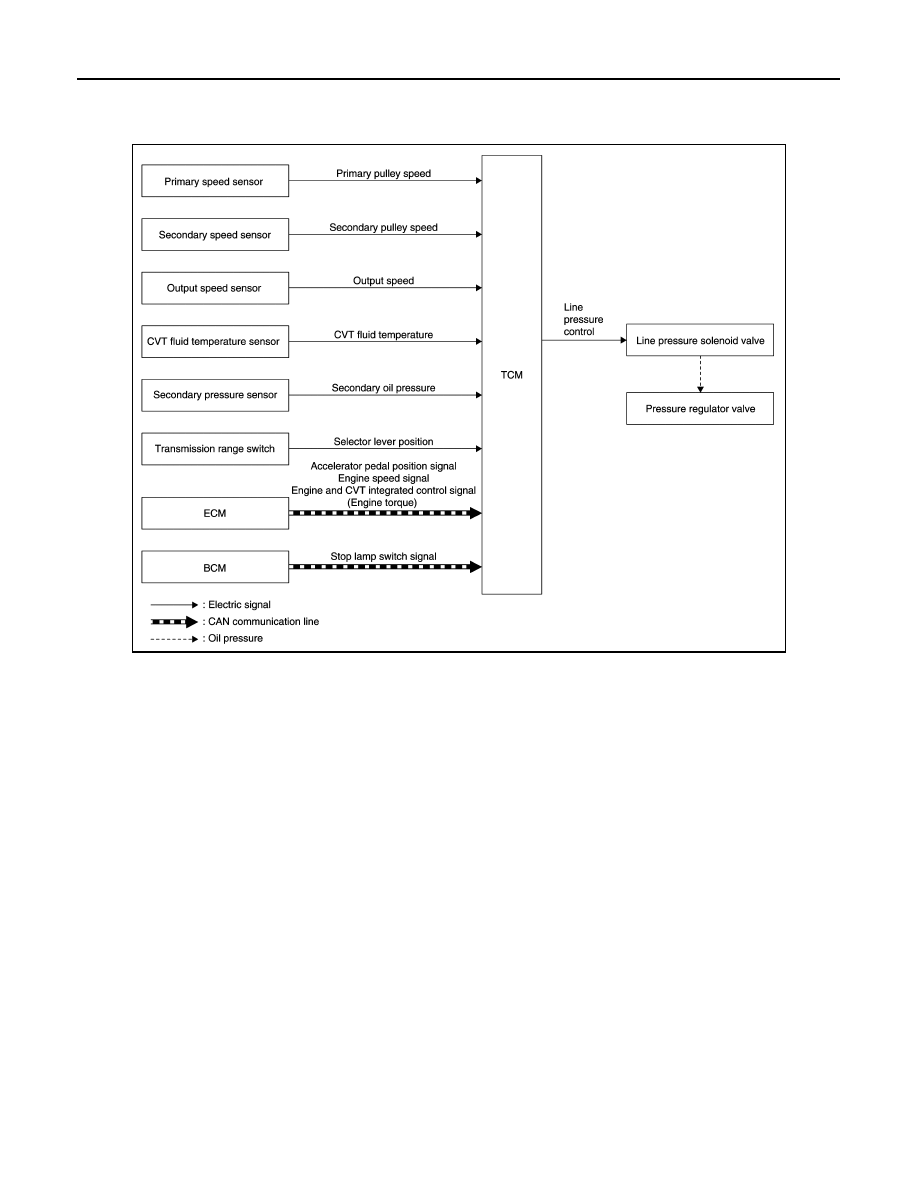
LINE PRESSURE CONTROL : System Description

INFOID:0000000009268088

SYSTEM DIAGRAM

DESCRIPTION

Highly accurate line pressure control (secondary pressure control) reduces friction for improvement of fuel

economy. 

Normal Oil Pressure Control

Appropriate line pressure and secondary pressure suitable for driving condition are determined based on the

accelerator pedal position, engine speed, primary pulley (input) speed, secondary pulley (output) speed, vehi-

cle speed, input torque, stop lamp switch signal, transmission range switch signal, lock-up signal, power volt-

age, target shift ratio, oil temperature and oil pressure. 

Secondary Pressure Feedback Control

In normal oil pressure control and oil pressure control in shifting, highly accurate secondary pressure is deter-

mined by detecting the secondary pressure using a oil pressure sensor and by feedback control. 

SHIFT CONTROL

JSDIA1864GB

SYSTEM

TM-283

< SYSTEM DESCRIPTION >

[CVT: RE0F11A]

C

E

F

G

H

I

J

K

L

M

A

B

TM

N

O

P

SHIFT CONTROL : System Description

INFOID:0000000009268089

SYSTEM DIAGRAM

DESCRIPTION

To select the gear ratio that can give the driving force to meet driver's intent or vehicle situation, the vehicle

driving condition such as vehicle speed or accelerator pedal position is detected and the most appropriate

gear ratio is selected and the shifting method before reaching the speed is determined.   The information is

output to the primary pressure solenoid valve to control the line pressure input/output to the primary pulley, to

determine the primary pulley (movable pulley) position and to control the gear position. 

D Position (Normal)

JSDIA2632GB

TM-284

< SYSTEM DESCRIPTION >

[CVT: RE0F11A]

SYSTEM

Gear shifting is performed in all shifting ranges from the lowest to the

highest gear ratio. 

D Position (Sport)

The gear ratio is generally high by limiting the shifting range on the

high side, and this always generates a large driving power. 

L Position

By limiting the shifting range only to the lowest of the gear ratio, a

large driving force and engine brake are obtained. 

Hill Climbing And Descending Control

If a downhill is detected with the accelerator pedal is released, the system performs downshift to increase the

engine brake force so that vehicle may not be accelerated more than necessary. If a climbing hill is detected,

the system improves the acceleration performance in re-acceleration by limiting the gear shift range on the

high side. 

NOTE:

For engine brake control on a downhill, the control can be stopped with CONSULT. 

Control In Acceleration

From change of the vehicle speed or accelerator pedal position, the acceleration request level of the driver or

driving scene is evaluated. In start or acceleration during driving, the gear shift characteristics with linearity of

revolution increase and vehicle speed increase are gained to improve the acceleration feel.

SELECT CONTROL

SCIA1953E

SCIA8229E

SCIA8240E

JSDIA2060GB

SYSTEM

TM-285

< SYSTEM DESCRIPTION >

[CVT: RE0F11A]

C

E

F

G

H

I

J

K

L

M

A

B

TM

N

O

P

SELECT CONTROL : System Description

INFOID:0000000009268090

SYSTEM DIAGRAM

DESCRIPTION

Based on accelerator pedal angle, engine speed, primary pulley speed, and the secondary pulley speed, the

optimum operating pressure is set to reduce impact of a selector lever operation while shifting from “N” (“P”) to

“D” (“R”) position.

LOCK-UP CONTROL

JSDIA1862GB


Content   ..  842  843  844  845   ..