Nissan Versa Sedan. Instruction - part 793


  Index      Nissan     Nissan Versa Sedan (2014 year) - Service and Repair Instruction


Search            copyright infringement  


Content   ..  791  792  793  794   ..


Nissan Versa Sedan. Instruction - part 793


TM-78

< SYSTEM DESCRIPTION >

[4AT: RE4F03C]

STRUCTURE AND OPERATION

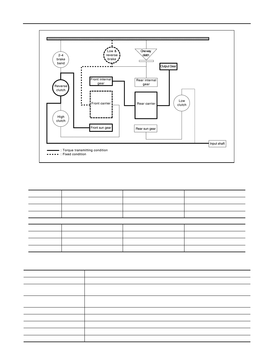
• The drive force from the input shaft is transmitted by forward rotation of the engaged reverse clutch to the

front sun gear. Engagement of the low & reverse brake fastens the front carrier in place, causing the front

internal gear to turn in reverse and transmitting force by reverse rotation to the output gear.

• The status of each planetary gear is as shown below.

Front planetary gear

Rear planetary gear

TRANSAXLE : Component Description

INFOID:0000000009267842

JSDIA1999GB

Name

Front sun gear

Front carrier

Front internal gear

Condition

Input

Fixed

Output

Rotating direction

Forward

Stopped

Reverse

Speed

Same speed as input shaft

Slower than input shaft

Name

Rear sun gear

Rear carrier

Rear internal gear

Condition

Fixed

Fixed

Rotating direction

Reverse

Reverse

Stopped

Speed

Faster than input shaft

Slower than input shaft

Name (abbreviation)

FUNCTION

Torque converter

Amplifies the drive force from the engine and transmits it to the transmission input shaft.

Oil pump

Driven by the engine, this component supplies oil to the torque converter, control valve assembly, 
and lubricated parts.

4-point gear

Transmits drive force from the transmission mechanism to the output gear, idler gear, reduction 
gear, and final gear.

Low clutch (L/C)

Connects the rear sun gear and input shaft

High clutch (H/C)

Connects the front carrier and input shaft

Reverse clutch (R/C)

Connects the front sun gear and input shaft

Low & reverse brake (L&R/B)

Fastens the rear internal gear and front carrier in place.

2-4 brake (2-4/B)

Brake band that fastens the front sun gear in place.

STRUCTURE AND OPERATION

TM-79

< SYSTEM DESCRIPTION >

[4AT: RE4F03C]

C

E

F

G

H

I

J

K

L

M

A

B

TM

N

O

P

SHIFT LOCK SYSTEM
SHIFT LOCK SYSTEM : System Description

INFOID:0000000009267855

The selector lever cannot be shifted from “P” position to any other position unless the ignition switch is in the

ON position and the brake pedal is depressed.

KEY LOCK SYSTEM
KEY LOCK SYSTEM : System Description

INFOID:0000000009267856

• The key lock mechanism also operates as a shift lock:

With the ignition switch turned to ON, selector lever cannot be shifted from “P” position to any other position

unless brake pedal is depressed.

With the key removed, selector lever cannot be shifted from “P” position to any other position.

The key cannot be removed unless selector lever is placed in “P” position.

• The shift lock and key lock mechanisms are controlled by the ON-OFF operation of the shift lock solenoid

and by the operation of the rotator and slider located inside key cylinder, respectively.

One-way clutch (OWC)

This clutch prevents reverse turning of the front carrier and rear internal gear. It operates not hy-
draulically but mechanically.

Planetary gear

Transmits drive force to various positions by engagement and release of the clutches and bands.

Name (abbreviation)

FUNCTION

TM-80

< SYSTEM DESCRIPTION >

[4AT: RE4F03C]

SYSTEM

SYSTEM

A/T CONTROL SYSTEM
A/T CONTROL SYSTEM : System Diagram

INFOID:0000000009267843

A/T CONTROL SYSTEM : System Description

INFOID:0000000009267844

SYSTEM DESCRIPTION

• The A/T senses vehicle operating conditions through various sensors or signals. It always controls the opti-

mum shift position and reduces shifting and lock-up shocks.

• Receives input signals transmitted from various switches and sensors.

• Determines required line pressure, shifting point, lock-up operation, etc.

• Transmits required output signals to the respective solenoids.

INPUT/OUTPUT SIGNAL CHART

INPUT/OUTPUT SIGNAL OF TCM

JSDIA2058GB

Sensor (or signal)

TCM function

Actuator

Engine speed signal
Engine torque signal
Accelerator pedal position signal
Closed throttle position signal
Stop lamp switch signal
Transmission range switch
O/D switch signal
A/T fluid temperature sensor
Input speed sensor
Output speed sensor
Vehicle speed signal

Line pressure control (

TM-84

)

Shift change control (

TM-86

)

Shift pattern control (

TM-87

)

Lock-up control (

TM-88

)

Fail-safe control (

TM-81

)

Self-diagnosis (

TM-93

)

CONSULT communication line (

TM-93

)

CAN communication line (

TM-137

)

Line pressure solenoid valve
Torque converter clutch solenoid valve
Low clutch solenoid valve 
2-4 brake solenoid valve
High clutch/low & reverse brake solenoid 
valve
Select switch ON-OFF solenoid valve 
Shift position indicator
O/D OFF indicator lamp

SYSTEM

TM-81

< SYSTEM DESCRIPTION >

[4AT: RE4F03C]

C

E

F

G

H

I

J

K

L

M

A

B

TM

N

O

P

*: If these input and output signals are different, the TCM triggers the fail-safe function.

A/T CONTROL SYSTEM : Fail-Safe

INFOID:0000000009267845

TCM is equipped with an electrical fail-safe mode. The operation can be continued even if the signal circuit of

the main electronically controlled input/output parts are damaged.

If the vehicle shows following behaviors including “poor acceleration”, a malfunction of the applicable system

is detected by TCM and the vehicle may be in a fail-safe mode. At this time, check the DTC code and perform

inspection and repair according to the malfunction diagnosis procedures.

FAIL-SAFE FUNCTION

Control item

Line

 pressure

 control

Shift change 

control

Shift pattern 

control

Lock-up con-

trol

Fail-safe func-

tion

*

Input

Engine speed signal
(CAN communication line)

X

X

X

X

X

Engine torque signal
(CAN communication line)

X

X

Accelerator pedal position signal 
(CAN communication line)

X

X

X

X

X

Closed throttle position signal
(CAN communication line)

X

X

X

X

Stop lamp switch signal
(CAN communication line)

X

X

X

X

Transmission range switch

X

X

X

X

X

O/D switch signal
(CAN communication line)

X

A/T fluid temperature sensor

X

X

X

X

X

Input speed sensor

X

X

X

X

Output pressure sensor

X

X

X

X

X

Output

Line pressure solenoid valve

X

X

X

Torque converter clutch solenoid 
valve

X

X

X

Low clutch solenoid valve

X

X

2-4 brake solenoid valve

X

X

High clutch/low & reverse brake sole-
noid valve

X

X

Select switch ON-OFF solenoid valve

X

X

Shift position indicator
(CAN communication line)

X

O/D OFF indicator lamp
(CAN communication line)

X

DTC

Vehicle behavior

Vehicle condition

P0705
P0706

• “D” position (The shifting can be performed)
• “R” position can be performed
• Back-up lamp is OFF
• Large shift shock
• Lock-up is prohibited
• Slip lock-up is prohibited

P0713

The gear is fixed in a position of error detection

During driving

Locks in 3GR

Other than the above


Content   ..  791  792  793  794   ..