Nissan Versa Sedan. Instruction - part 752
ST-10
< REMOVAL AND INSTALLATION >
STEERING COLUMN
• When removing intermediate shaft, do not insert any tool into the yoke groove to pull out the
intermediate shaft or damage could occur. Replace intermediate shaft with a new one if dam-
aged.
15. Disconnect the harness connectors from EPS control unit.
16. Remove steering column assembly.
17. Remove EPS control unit from steering column assembly. Refer to
STC-40, "Removal and Installation"
.
18. Remove clamp from steering column assembly.
19. Perform inspection after removal. Refer to
INSTALLATION
CAUTION:
• Do not impact on the axis when removing steering column assembly.
• When installing the steering column cover, check that the vehicle harness is not stuck in the cover.
Installation is in the reverse order of removal.
• For intermediate shaft bolt direction, refer to
.
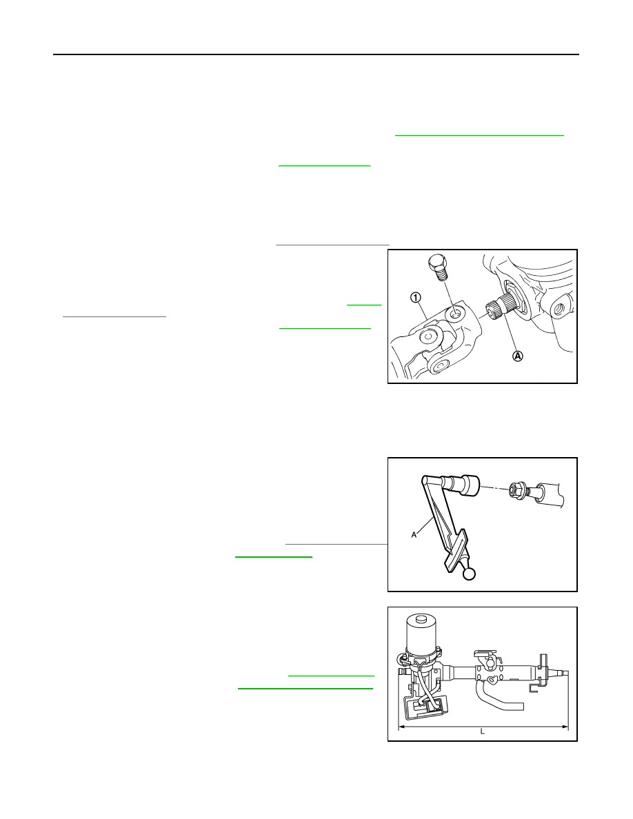
• When connecting intermediate shaft upper side (1) and column
shaft, make sure the bolt is securely seated in groove (A) of col-
umn shaft before final tightening.
• After installing steering column assembly, perform self-diagnosis
with CONSULT to ensure correct operation. Refer to
• Perform inspection after installation. Refer to
.
Inspection
INFOID:0000000009266814
INSPECTION AFTER REMOVAL
• Check each part of steering column assembly for damage or other malfunctions. Replace if there are any
abnormal conditions.
• Measure steering column rotating torque using Tool (A). Replace
steering column assembly if the rotating torque is outside the stan-
dard.
• Measure the steering column length (L) as shown, if vehicle has
been involved in a minor collision. Replace steering column
assembly (with motor, reduction gear, sensor) if (L) is outside the
standard.
INSPECTION AFTER INSTALLATION
• Check each part of steering column assembly for damage or other malfunctions. Replace if there are any
abnormal conditions.
SGIA1295E
Tool number
:
—
(J-25765-A)
Rotating torque
.
JPGIA0085ZZ
Steering column length (L) : Refer to
.
JPGIA0111ZZ