Nissan Versa Sedan. Instruction - part 686


  Index      Nissan     Nissan Versa Sedan (2014 year) - Service and Repair Instruction


Search            copyright infringement  


Content   ..  684  685  686  687   ..


Nissan Versa Sedan. Instruction - part 686


SEC-16

< SYSTEM DESCRIPTION >

[WITH INTELLIGENT KEY SYSTEM]

SYSTEM

NISSAN ANTI-THEFT SYSTEM : System Description

INFOID:0000000009268370
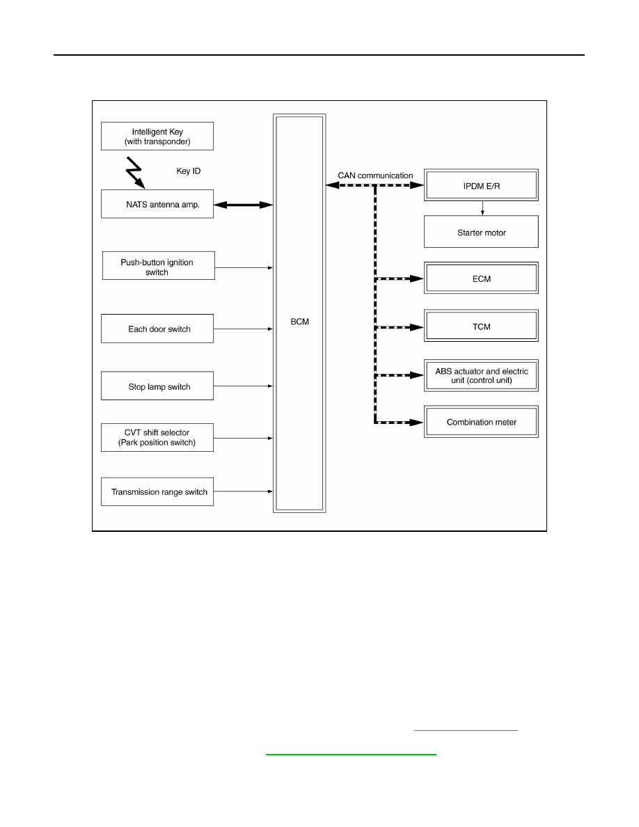
SYSTEM DIAGRAM

SYSTEM DESCRIPTION

• The Nissan Anti-Theft System (NATS) prevents the engine from being started by Intelligent Key whose ID is

not registered to the vehicle (BCM). It has higher protection against auto theft involving the duplication of

mechanical keys.

• The ignition key integrated in the Intelligent Key cannot start the engine. When the Intelligent Key battery is

discharged, the NATS ID verification is performed between the transponder integrated with Intelligent Key

and BCM via NATS antenna amp. when the Intelligent Key backside is contacted to push-button ignition

switch while brake pedal is depressed. If the verification result is OK, the engine start operation can be per-

formed by the push-button ignition switch operation.

• Locate the security indicator lamp and always blinks it when the ignition switch is in any position except ON

to warn that the vehicle is equipped with Nissan Anti-Theft System (NATS).

• Up to 4 Intelligent Keys can be registered (including the standard ignition key) upon request from the owner.

• When replacing ECM, BCM or Intelligent Key, the specified procedure (Initialization and registration) using

CONSULT is required.

• Possible symptom of NATS malfunction is “Engine can not start”. This symptom also occurs because of

other than NATS malfunction, so start the trouble diagnosis according to 

SEC-47, "Work Flow"

.

• If ECM other than genuine part is installed, the engine cannot be started.

For ECM replacement procedure, refer to 

EC-463, "Removal and Installation"

.

PRECAUTIONS FOR KEY REGISTRATION

ALKIA2829GB

SYSTEM

SEC-17

< SYSTEM DESCRIPTION >

[WITH INTELLIGENT KEY SYSTEM]

C

D

E

F

G

H

I

J

L

M

A

B

SEC

N

O

P

• The ID registration is a procedure that erases the current NATS ID once, and then registers a new ID. There-

fore before starting the registration operation, collect all registered Intelligent Keys from the customer.

• When registering the Intelligent Key, perform only one procedure to simultaneously register both IDs (NATS

ID and Intelligent Key ID).

SECURITY INDICATOR LAMP

• Security indicator lamp warns that the vehicle is equipped with NATS.

• Security indicator lamp always blinks when the ignition switch is in any position other than ON.

NOTE:

Because security indicator lamp is highly efficient, the battery is barely affected.

ENGINE START OPERATION WHEN INTELLIGENT KEY IS CONTACTED TO PUSH-BUTTON IG-
NITION SWITCH

1. When brake pedal is depressed while selector lever is in the P position the BCM activates NATS antenna

amp. that is located behind push-button ignition switch.

2. When Intelligent Key (transponder built-in) backside is contacted to push-button ignition switch, BCM

starts NATS ID verification between BCM and Intelligent Key (transponder built-in) via NATS antenna

amp.

3. When NATS ID verification result is OK, buzzer in combination meter sounds and BCM transmits the

result to ECM.

4. BCM turns ACC relay ON and transmits ignition power supply ON signal to IPDM E/R.
5. IPDM E/R turns the ignition relay ON and starts the ignition power supply.
6. IPDM E/R turns the starter control relay ON for engine starting in advance.
7. BCM detects that the selector lever position and brake pedal operation condition.
8. BCM transmits starter request signal to IPDM E/R and turns the starter relay in IPDM E/R ON if BCM

judges that the engine start condition* is satisfied.

9. Power supply is supplied through the starter relay and the starter control relay to operate the starter motor.
10. When BCM receives feedback signal from ECM indicating that the engine is started, BCM transmits a

stop signal to IPDM E/R and stops cranking by turning off the starter motor relay. (If engine start is unsuc-

cessful, cranking stops automatically within 5 seconds.)

*: For the engine start condition, refer to “IGNITION SWITCH POSITION CHANGE TABLE BY PUSH-BUT-

TON IGNITION SWITCH OPERATION” below.

IGNITION SWITCH POSITION CHANGE TABLE BY PUSH-BUTTON IGNITION SWITCH OPERA-
TION

The ignition switch position can be changed by the following operations.

NOTE:

• When an Intelligent Key is within the detection area of inside key antenna or when Intelligent Key backside is

contacted to push-button ignition switch, it is equivalent to the operations below.

• When starting the engine, the BCM monitors under the engine start conditions,

- Brake pedal operation condition

- Selector lever position

- Vehicle speed

Vehicle speed: less than 4 km/h (2.5 MPH)

Power supply position

Condition

Push-button ignition switch 

operation frequency

Selector lever

Brake pedal operation 

condition

OFF 

→ ACC

Not depressed

1

OFF 

→ ACC → ON

Not depressed

2

OFF 

→ ACC → ON → 

OFF

Not depressed

3

SEC-18

< SYSTEM DESCRIPTION >

[WITH INTELLIGENT KEY SYSTEM]

SYSTEM

Vehicle speed: 4 km/h (2.5 MPH) or more

Emergency stop operation
• Press and hold the push-button ignition switch for 2 seconds or more.
• Press the push-button ignition switch 3 times or more within 1.5 seconds.

VEHICLE SECURITY SYSTEM
VEHICLE SECURITY SYSTEM : System Description

INFOID:0000000009268371

• The vehicle security system has two alarm functions (theft warning alarm and panic alarm) and reduces the

possibility of a theft or mischief by activating horns and headlamps intermittently.

• The panic alarm does not start when the theft warning alarm is activating and the panic alarm stops when

the theft warning alarm is activated.

The priority of the functions are as per the following.

THEFT WARNING ALARM

• The theft warning alarm function activates horns and headlamps intermittently when BCM detects that any

door or hood is opened by unauthorized means while the system is in the ARMED state.

• Security indicator lamp on combination meter always blinks when power supply position is any position other

than ON. Security indicator lamp blinking warns that the vehicle is equipped with a vehicle security system.

Operation Flow

OFF 

→ START

ACC 

→ START

ON 

→ START

P or N position

Depressed

1

Engine is running 

→ 

OFF

1

Power supply position

Condition

Push-button ignition switch 

operation frequency

Selector lever

Brake pedal operation 

condition

Power supply position

Condition

Push-button ignition switch 

operation frequency

Selector lever

Brake pedal operation 

condition

Engine is running 

→ 

ACC 

Emergency stop operation

Engine stall return oper-
ation while driving 

N position

Not depressed

1

Priority

Function

1

Theft warning alarm

2

Panic alarm

JMKIA5416GB

SYSTEM

SEC-19

< SYSTEM DESCRIPTION >

[WITH INTELLIGENT KEY SYSTEM]

C

D

E

F

G

H

I

J

L

M

A

B

SEC

N

O

P

NOTE:
• BCM ignores the door key cylinder UNLOCK switch signal input for 1 second after the door key cylinder LOCK switch signal input.
• To lock/unlock all doors by operating remote controller button of Intelligent Key or door request switch, Intelligent Key must be within

the detection area of outside key antenna. For details, refer to 

SEC-13, "INTELLIGENT KEY SYSTEM/ENGINE START FUNCTION :

System Description"

.

• To open trunk by operating trunk opener switch, Intelligent Key must be within the detection area of outside key antenna. For details,

refer to 

SEC-13, "INTELLIGENT KEY SYSTEM/ENGINE START FUNCTION : System Description"

.

DISARMED Phase

No.

System state

Switching condition

1

DISARMED to 
PRE-ARMED

When all conditions of A and 
one condition of B is satis-
fied.

A

B

• Power supply position: OFF/LOCK
• All doors: Closed
• Hood: Closed

All doors are locked by:
• Door key cylinder LOCK switch
• LOCK button of Intelligent Key
• Door request switch

2

PRE-ARMED 
to ARMED

When all of the following 
conditions are satisfied for 
30 seconds.

• Power supply position: OFF/LOCK
• All doors: Locked
• Hood: Closed

3

ARMED  to 
ALARM

When one condition of A and 
one condition of B are satis-
fied.

A

B

Intelligent Key: Not used

• Any door: Open
• Hood: Open

4

DISARMED to 
PRE-RESET

When all conditions of A and 
one condition of B is satis-
fied.

A

B

• Power supply position: OFF/LOCK
• All doors: Closed
• Hood: Open

All doors are locked by:
• Door key cylinder LOCK switch
• LOCK button of Intelligent Key
• Door request switch

5

PRE-ARMED 
to PRE-RESET

When one of the following 
conditions is satisfied.

• Hood: Open

6

ARMED  to 
PRE-RESET

No conditions.

7

ALARM to 
PRE-RESET

8

PRE-RESET to 
DISARMED

When one of the following 
conditions is satisfied.

• Power supply position: ACC/ON/CRANKING/RUN
• Door key cylinder UNLOCK switch: ON
• UNLOCK button of Intelligent Key: ON
• Door request switch: ON
• Trunk opener switch: ON
• UNLOCK switch of door lock and unlock switch: ON
• Any door: Open

9

PRE-RESET to 
PRE-ARMED

When all of the following 
conditions are satisfied.

• Power supply position: OFF/LOCK
• All doors: Closed
• Hood: Closed

10

PRE-ARMED 
to DISARMED

When one of the following 
conditions is satisfied.

• Power supply position: ACC/ON/CRANKING/RUN
• Door key cylinder UNLOCK switch: ON
• UNLOCK button of Intelligent Key: ON
• TRUNK button of Intelligent Key: ON
• Door request switch: ON
• Trunk opener switch: ON
• Any door: Open

11

ARMED to 
DISARMED

When one of the following 
conditions is satisfied.

• Power supply position: ACC/ON/CRANKING/RUN
• Door key cylinder UNLOCK switch: ON
• UNLOCK button of Intelligent Key: ON
• Door request switch: ON
• Trunk opener switch: ON

12

ALARM to 
DISARMED

13

RE-ALARM

When one of the following 
conditions is satisfied after 
the ALARM operation is fin-
ished.

• Any door: Open
• Hood: Open


Content   ..  684  685  686  687   ..