Nissan Versa Sedan. Instruction - part 580
MWI
DIAGNOSIS SYSTEM (COMBINATION METER)
MWI-19
< SYSTEM DESCRIPTION >
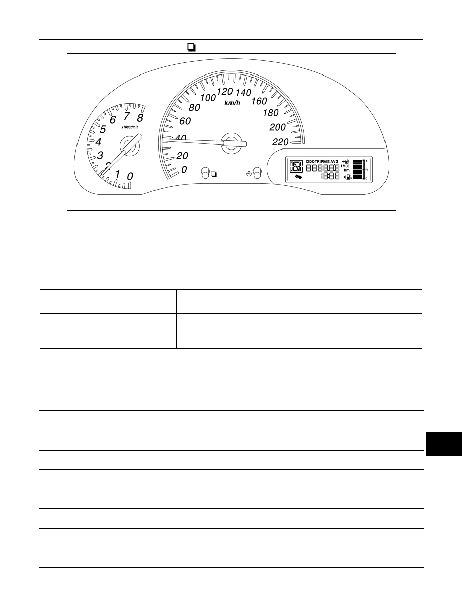
[TYPE A]
C
D
E
F
G
H
I
J
K
L
M
B
A
O
P
5. Each meter activates by pressing the switch.
NOTE:
• If any of the meters or gauges is not activated, replace combination meter.
• The figure is reference.
CONSULT Function
INFOID:0000000009266579
APPLICATION ITEMS
CONSULT can display each diagnostic item using the diagnostic test modes shown.
SELF DIAG RESULT
.
DATA MONITOR
Display Item List
X: Applicable
JSNIA3903ZZ
METER/M&A Diagnosis mode
Description
SELF DIAGNOSTIC RESULT
The combination meter self-diagnosis results.
DATA MONITOR
Displays combination meter input/output data in real time.
SPECIAL FUNCTION
Lighting history of the warning lamp and indicator lamp can be checked.
CAN DIAG SUPPORT MNTR
The result of transmit/receive diagnosis of CAN communication can be read.
Display item [Unit]
MAIN
SIGNALS
Description
SPEED METER
[km/h] or [mph]
X
Displays the value of vehicle speed signal.
SPEED OUTPUT
[km/h] or [mph]
X
Displays the value of vehicle speed signal, which is transmitted to each unit with
CAN communication.
ODO OUTPUT
[km/h or mph]
Displays odometer signal value transmitted to other units via CAN communica-
tion.
TACHO METER
[rpm]
X
Displays the value of engine speed signal, which is input from ECM.
FUEL METER
[L]
X
Displays the fuel level.
W TEMP METER
[
°C] or [°F]
X
Displays the value of engine coolant temperature signal, which is input from ECM.
ABS W/L
[ON/OFF]
Displays [ON/OFF] condition of ABS warning indicator