Nissan Versa Sedan. Instruction - part 564


  Index      Nissan     Nissan Versa Sedan (2014 year) - Service and Repair Instruction


Search            copyright infringement  


Content   ..  562  563  564  565   ..


Nissan Versa Sedan. Instruction - part 564


MA-14

< PERIODIC MAINTENANCE >

ENGINE MAINTENANCE

ENGINE MAINTENANCE

DRIVE BELT
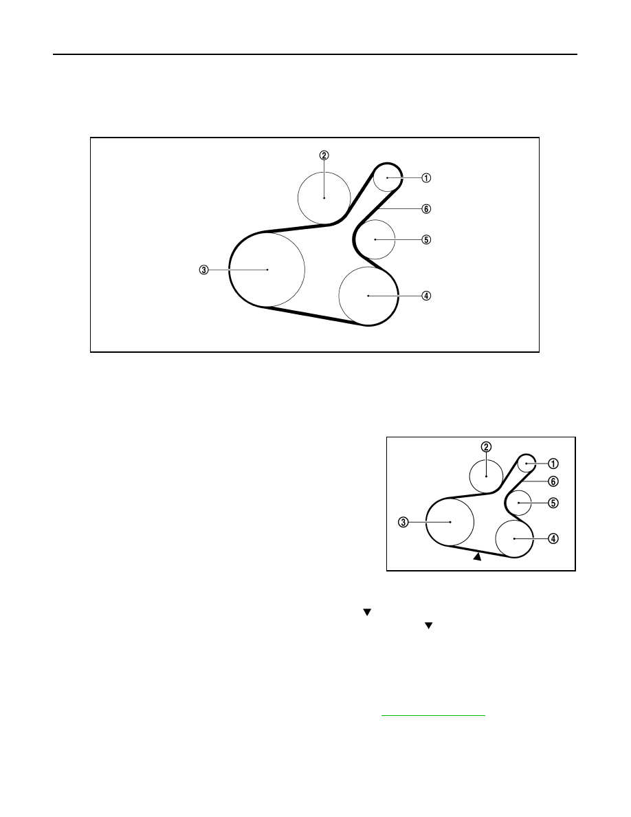
DRIVE BELT : Exploded View

INFOID:0000000009269041

DRIVE BELT : Inspection

INFOID:0000000009269042

• Inspection should be done only when engine is cold or over 30

minutes after the engine is stopped.

• Visually check belt for wear, damage, and cracks on inside and

edges.

• Turn crankshaft pulley clockwise twice, and check that the tension on all pulleys equalizes before testing. 
• When measuring deflection, apply 98.1 N (10 kg, 22 lb) at the ( ) marked point.
• Measure the belt tension and frequency with acoustic tension gauge at the ( ) marked point.

CAUTION:

• When the tension and frequency are measured, the acoustic tension gauge should be used.

• When checking immediately after installation, first adjust it to the specified value. Then, after turning

crankshaft two turns or more, readjust to the specified value to avoid variation in deflection between

pulleys.

1.

Generator

2.

Water pump

3.

Crankshaft pulley

4.

A/C compressor (with A/C models)
Idler pulley (without A/C models)

5.

Idler pulley

6.

Drive belt

JSBIA1053ZZ

(1)

: Generator

(2)

: Water pump

(3)

: Crankshaft pulley

(4)

: A/C compressor (with A/C models)
: Idler pulley (without A/C models)

(5)

: Idler pulley

(6)

: Drive belt

Belt deflection/belt tension and frequency

: Refer to 

EM-117, "Drive Belt"

.

PBIC3642E

ENGINE MAINTENANCE

MA-15

< PERIODIC MAINTENANCE >

C

D

E

F

G

H

I

J

K

L

M

B

MA

N

O

A

DRIVE BELT : Adjustment

INFOID:0000000009269043

CAUTION:

• When belt is replaced with new one, adjust belt tension to the value for “New belt,” because new belt

will not fully seat in the pulley groove.

• When tension of the belt being used exceeds “Limit,” adjust it to the value for “After adjusted.”

• When installing a belt, check it is correctly engaged with the pulley groove.

• Do not allow oil or engine coolant to get on the belt.

• Do not twist or bend the belt strongly.
1. Remove the fender protector (RH) front side clip. Refer to 

EXT-26, "Removal and Installation"

.

2. Tighten lock nut (A) temporarily to the following torque.

3. Adjust the belt tension by turning the adjusting bolt. Refer to 

EM-117, "Drive Belt"

.

CAUTION:

• When checking immediately after installation, first adjust it to the specified value. Then, after

turning crankshaft two turns or more, readjust to the specified value to avoid variation in deflec-

tion between pulleys.

• When the tension adjustment is performed, the lock nut should be in the condition at Step 2. If

the tension adjustment is performed when the lock nut is loosened more than the temporary

tightening, the idler pulley tilts and the correct tension adjustment cannot be performed.

4. Tighten the lock nut to final tightening specification.

ENGINE COOLANT
ENGINE COOLANT : Inspection

INFOID:0000000009269044

CHECKING COOLING SYSTEM HOSES

Check hoses for the following:

• Improper attachment

• Leaks

• Cracks

• Damage

• Loose connections

• Chafing

• Deterioration

CHECKING RESERVOIR LEVEL 

Location

Location of adjuster and tightening method

Drive belt

Adjusting bolt on idler pulley

Lock nut (A)
(Temporary tightening)

: 4.4 N·m (0.45 kg-m, 39 in-lb)

(1)

: Generator

(2)

: Water pump

(3)

: Crankshaft pulley

(4)

: A/C compressor (with A/C models)
: Idler pulley (without A/C models)

(5)

: Idler pulley

(6)

: Drive belt

(B)

: Adjusting bolt

PBIC3643E

Lock nut (Final tightening)

: 34.8 N·m (3.5 kg-m, 26 ft-lb)

MA-16

< PERIODIC MAINTENANCE >

ENGINE MAINTENANCE

• Check that the reservoir tank engine coolant level is within the

MAX (A) to MIN (B) range when the engine is cool.

• Adjust the engine coolant level if necessary.

CAUTION:

Refill the engine cooling system with the specified coolant or

equivalent. Refer to 

MA-12, "Fluids and Lubricants"

.

ENGINE COOLANT : Draining Engine Coolant

INFOID:0000000009269045

WARNING:

• Do not remove radiator cap when engine is hot. Serious burns could occur from high-pressure

engine coolant escaping from radiator. 

• Wrap a thick cloth around the radiator cap. Slowly turn it a quarter of a turn to release built-up pres-

sure. Then turn it all the way.

1. Remove engine under cover. Refer to 

EXT-15, "Exploded View"

.

2. Connect a drain hose to the radiator drain plug.

• Use a suitable hose with the dimensions as shown.

3. Open radiator drain plug (A) at the bottom of radiator, and then

remove radiator cap. 

 : Front

CAUTION:

• Perform this step when engine is cold.

• Do not spill engine coolant on the drive belt.

4. It is necessary to drain the cylinder block when draining all of engine coolant in the system. To drain the

cylinder block, open the water drain plugs on cylinder block. Refer to 

EM-94, "Exploded View"

.

5. Remove reservoir tank if necessary, and drain engine coolant and clean reservoir tank before installing.

Refer to 

CO-14, "Exploded View"

.

6. Check drained engine coolant for contaminants such as rust, corrosion or discoloration. If contaminated,

flush the engine cooling system. Refer to 

MA-18, "ENGINE COOLANT : Flushing Cooling System"

.

ENGINE COOLANT : Refilling Engine Coolant

INFOID:0000000009269046

1. Install the radiator drain plug. Install the reservoir tank and cylinder block drain plug, if removed.

CAUTION:

• Be sure to clean drain plug and install with a new O-ring.

• Apply sealant to the threads of the cylinder block drain plug. Use Genuine High Performance

Thread Sealant or equivalent. Refer to 

GI-21, "Recommended Chemical Products and Sealants"

.

JPBIA0102ZZ

Diameter (A)

: 0.8 mm (0.31 in)

Length (B)

: 300 mm (11.81 in)

JPBIA4770ZZ

JSBIA1090ZZ

ENGINE MAINTENANCE

MA-17

< PERIODIC MAINTENANCE >

C

D

E

F

G

H

I

J

K

L

M

B

MA

N

O

A

2. Set the vehicle heater controls to the full HOT and heater ON position. Turn the vehicle ignition ON with

the engine OFF as necessary to activate the heater mode.

3. Install the Tool by installing the radiator cap adapter onto the

radiator neck opening. Then attach the gauge body assembly

with the refill tube and the venturi assembly to the radiator cap

adapter.

4. Insert the refill hose into the coolant mixture container that is

placed at floor level. Make sure the ball valve is in the closed

position. 

CAUTION:

Do not use any cooling system additives such as radiator

sealer. Additives may clog the cooling system and cause

damage to the engine, transmission and/or cooling system.

NOTE:

Use recommended coolant or equivalent. Refer to 

MA-12, "Flu-

ids and Lubricants"

.

5. Install an air hose to the venturi assembly. The air pressure must

be within specification. 

CAUTION:

The compressed air supply must be equipped with an air dryer.

6. The vacuum gauge will begin to rise and there will be an audible hissing noise. During this process open

the ball valve on the refill hose slightly. Coolant will be visible rising in the refill hose. Once the refill hose is

full of coolant, close the ball valve. This will purge any air trapped in the refill hose.

7. Continue to draw the vacuum until the gauge reaches 28 inches

of vacuum. The gauge may not reach 28 inches in high altitude

locations; use the vacuum specifications based on the altitude

above sea level.

8. When the vacuum gauge has reached the specified amount, disconnect the air hose and wait 20 seconds

to see if the system loses any vacuum. If the vacuum level drops, perform any necessary repairs to the

system and repeat steps 6 - 8 to bring the vacuum to the specified amount. Recheck for any leaks. 

9. Place the coolant container (with the refill hose inserted) at the same level as the top of the radiator. Then

open the ball valve on the refill hose so the coolant will be drawn up to fill the cooling system. The cooling

system is full when the vacuum gauge reads zero.

CAUTION:

Do not allow the coolant container to get too low when filling, to avoid air from being drawn into

the cooling system. 

Radiator drain plug

: Refer to 

CO-14, "Exploded View"

.

Cylinder block drain plug

: Refer to 

EM-94, "Exploded View"

.

Tool number

: KV991J0070 (J-45695)

Engine coolant capacity 
(with reservoir tank)

: Refer to 

MA-12, "Fluids 

and Lubricants"

.

Compressed air 
supply pressure

: 549 - 824 kPa (5.6 - 8.4 kg/cm

2

80 - 119 psi)

LLIA0058E

Altitude above sea level

Vacuum gauge reading

0 - 100 m (328 ft)

: 28 inches of vacuum

300 m (984 ft)

: 27 inches of vacuum

500 m (1,641 ft)

: 26 inches of vacuum

1,000 m (3,281 ft)

: 24 - 25 inches of vacuum

LLIA0057E


Content   ..  562  563  564  565   ..