Nissan Versa Sedan. Instruction - part 553


  Index      Nissan     Nissan Versa Sedan (2014 year) - Service and Repair Instruction


Search            copyright infringement  


Content   ..  551  552  553  554   ..


Nissan Versa Sedan. Instruction - part 553


LAN-90

< DTC/CIRCUIT DIAGNOSIS >

[CAN SYSTEM (TYPE 4)]

MAIN LINE BETWEEN IPDM-E AND DLC CIRCUIT

DTC/CIRCUIT DIAGNOSIS

MAIN LINE BETWEEN IPDM-E AND DLC CIRCUIT

Diagnosis Procedure

INFOID:0000000009642886

1.

CHECK CONNECTOR

1. Turn the ignition switch OFF.

2. Disconnect the battery cable from the negative terminal.

3. Check the following terminals and connectors for damage, bend and loose connection (connector side

and harness side).

-

Harness connector E7

-

Harness connector M69

Is the inspection result normal?

YES

>> GO TO 2.

NO

>> Repair the terminal and connector.

2.

CHECK HARNESS CONTINUITY (OPEN CIRCUIT)

1. Disconnect the following harness connectors.

-

IPDM E/R

-

Harness connectors E7 and M69

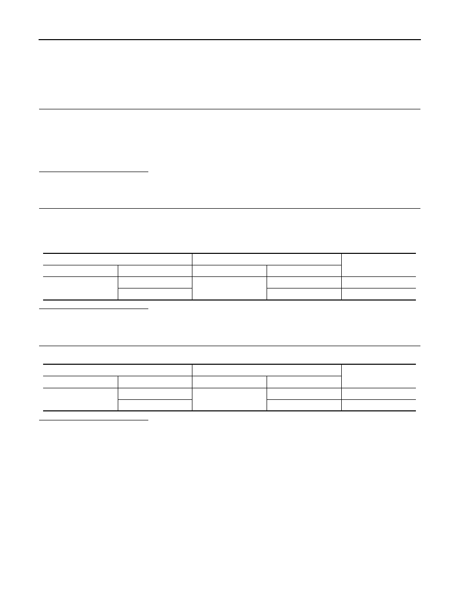
2. Check the continuity between the IPDM E/R harness connector and the harness connector.

Is the inspection result normal?

YES

>> GO TO 3.

NO

>> Repair the main line between the IPDM E/R and the harness connector E7.

3.

CHECK HARNESS CONTINUITY (OPEN CIRCUIT)

Check the continuity between the harness connector and the data link connector.

Is the inspection result normal?

YES (Present error)>>Check CAN system type decision again.

YES (Past error)>>Error was detected in the main line between the IPDM E/R and the data link connector. 

NO

>> Repair the main line between the harness connector M69 and the data link connector.

IPDM E/R harness connector

Harness connector

Continuity

Connector No.

Terminal No.

Connector No.

Terminal No.

E46

62

E7

21A

Existed

61

20A

Existed

Harness connector

Data link connector

Continuity

Connector No.

Terminal No.

Connector No.

Terminal No.

M69

21A

M22

6

Existed

20A

14

Existed

LAN

ECM BRANCH LINE CIRCUIT

LAN-91

< DTC/CIRCUIT DIAGNOSIS >

[CAN SYSTEM (TYPE 4)]

C

D

E

F

G

H

I

J

K

L

B

A

O

P

N

ECM BRANCH LINE CIRCUIT

Diagnosis Procedure

INFOID:0000000009642887

1.

CHECK CONNECTOR

1. Turn the ignition switch OFF.

2. Disconnect the battery cable from the negative terminal.

3. Check the terminals and connectors of the ECM for damage, bend and loose connection (unit side and

connector side).

Is the inspection result normal?

YES

>> GO TO 2.

NO

>> Repair the terminal and connector.

2.

CHECK HARNESS FOR OPEN CIRCUIT

1. Disconnect the connector of ECM.

2. Check the resistance between the ECM harness connector terminals.

Is the measurement value within the specification?

YES

>> GO TO 3.

NO

>> Repair the ECM branch line.

3.

CHECK POWER SUPPLY AND GROUND CIRCUIT

Check the power supply and the ground circuit of the ECM. Refer to 

EC-155, "Diagnosis Procedure"

.

Is the inspection result normal?

YES (Present error)>>Replace the ECM. Refer to 

EC-463, "Removal and Installation"

.

YES (Past error)>>Error was detected in the ECM branch line.

NO

>> Repair the power supply and the ground circuit.

ECM harness connector

Resistance (

Ω)

Connector No.

Terminal No.

E16

84

83

Approx. 108 – 132

LAN-92

< DTC/CIRCUIT DIAGNOSIS >

[CAN SYSTEM (TYPE 4)]

ABS BRANCH LINE CIRCUIT

ABS BRANCH LINE CIRCUIT

Diagnosis Procedure

INFOID:0000000009642888

1.

CHECK CONNECTOR

1. Turn the ignition switch OFF.

2. Disconnect the battery cable from the negative terminal.

3. Check the terminals and connectors of the ABS actuator and electric unit (control unit) for damage, bend

and loose connection (unit side and connector side).

Is the inspection result normal?

YES

>> GO TO 2.

NO

>> Repair the terminal and connector.

2.

CHECK HARNESS FOR OPEN CIRCUIT

1. Disconnect the connector of ABS actuator and electric unit (control unit).

2. Check the resistance between the ABS actuator and electric unit (control unit) harness connector termi-

nals.

Is the measurement value within the specification?

YES

>> GO TO 3.

NO

>> Repair the ABS actuator and electric unit (control unit) branch line.

3.

CHECK POWER SUPPLY AND GROUND CIRCUIT

Check the power supply and the ground circuit of the ABS actuator and electric unit (control unit). Refer to

BRC-61, "Diagnosis Procedure"

.

Is the inspection result normal?

YES (Present error)>>Replace the ABS actuator and electric unit (control unit). Refer to 

BRC-108, "Removal

and Installation"

.

YES (Past error)>>Error was detected in the ABS actuator and electric unit (control unit) branch line.

NO

>> Repair the power supply and the ground circuit.

ABS actuator and electric unit (control unit) harness connector

Resistance (

Ω)

Connector No.

Terminal No.

E33

26

14

Approx. 54 – 66

LAN

IPDM-E BRANCH LINE CIRCUIT

LAN-93

< DTC/CIRCUIT DIAGNOSIS >

[CAN SYSTEM (TYPE 4)]

C

D

E

F

G

H

I

J

K

L

B

A

O

P

N

IPDM-E BRANCH LINE CIRCUIT

Diagnosis Procedure

INFOID:0000000009642889

1.

CHECK CONNECTOR

1. Turn the ignition switch OFF.

2. Disconnect the battery cable from the negative terminal.

3. Check the terminals and connectors of the IPDM E/R for damage, bend and loose connection (unit side

and connector side).

Is the inspection result normal?

YES

>> GO TO 2.

NO

>> Repair the terminal and connector.

2.

CHECK HARNESS FOR OPEN CIRCUIT

1. Disconnect the connector of IPDM E/R.

2. Check the resistance between the IPDM E/R harness connector terminals.

Is the measurement value within the specification?

YES

>> GO TO 3.

NO

>> Repair the IPDM E/R branch line.

3.

CHECK POWER SUPPLY AND GROUND CIRCUIT

Check the power supply and the ground circuit of the IPDM E/R. Refer to the following.

• With Intelligent Key system: 

PCS-29, "Diagnosis Procedure"

• Without Intelligent Key system: 

PCS-55, "Diagnosis Procedure"

Is the inspection result normal?

YES (Present error)>>Replace the IPDM E/R. Refer to the following.

• With Intelligent Key system: 

PCS-30, "Removal and Installation"

• Without Intelligent Key system: 

PCS-56, "Removal and Installation"

YES (Past error)>>Error was detected in the IPDM E/R branch line.

NO

>> Repair the power supply and the ground circuit.

IPDM E/R harness connector

Resistance (

Ω)

Connector No.

Terminal No.

E46

62

61

Approx. 54 – 66


Content   ..  551  552  553  554   ..