Nissan Versa Sedan. Instruction - part 536


  Index      Nissan     Nissan Versa Sedan (2014 year) - Service and Repair Instruction


Search            copyright infringement  


Content   ..  534  535  536  537   ..


Nissan Versa Sedan. Instruction - part 536


LAN-22

< PRECAUTION >

[CAN]

PRECAUTIONS

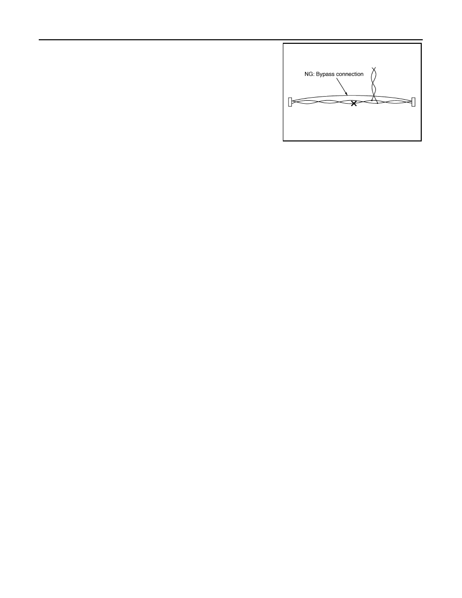
• Bypass connection is never allowed at the repaired area.

NOTE:

Bypass connection may cause CAN communication error. The

spliced wire becomes separated and the characteristics of twisted

line are lost. 

• Replace the applicable harness as an assembly if error is detected on the shield lines of CAN communica-

tion line.

SKIB8767E

LAN

COMPONENT PARTS

LAN-23

< SYSTEM DESCRIPTION >

[CAN]

C

D

E

F

G

H

I

J

K

L

B

A

O

P

N

SYSTEM DESCRIPTION

COMPONENT PARTS

Component Parts Location

INFOID:0000000009269350

1.

Combination meter
• M82: TYPE A
• M24: TYPE B

2.

AV control unit M70

3.

ABS actuator and electric unit (con-
trol unit) E33

4.

TCM
• F44: CVT models
• F57:  A/T  models

5.

ECM E16

6.

IPDM E/R E46

7.

EPS control unit M53

8.

BCM
• M97: Models with Intelligent Key 

system

• M18: Models without Intelligent 

Key system

9.

Data link connector M22

10. Steering angle sensor M64

11. Air bag diagnosis sensor unit M35 

ALMIA0647ZZ

LAN-24

< SYSTEM DESCRIPTION >

[CAN]

SYSTEM

SYSTEM

CAN COMMUNICATION SYSTEM
CAN COMMUNICATION SYSTEM : System Description

INFOID:0000000009269351

SYSTEM DIAGRAM

DESCRIPTION

CAN (Controller Area Network) is a serial communication line for real time application. It is an on-vehicle mul-

tiplex communication line with high data communication speed and excellent error detection ability. Many elec-

tronic control units are equipped onto a vehicle, and each control unit shares information and links with other

control units during operation (not independent). In CAN communication, control units are connected with 2

communication lines (CAN-H line, CAN-L line) allowing a high rate of information transmission with less wiring.

Each control unit transmits/receives data but selectively reads required data only.

CAN COMMUNICATION SIGNAL GENERATION

• Termination circuits (resistors) are connected across the CAN communication system. When transmitting a

CAN communication signal, each control unit passes a current to the CAN-H line and the current returns to

the CAN-L line.

JSMIA1470GB

JSMIA0450GB

LAN

SYSTEM

LAN-25

< SYSTEM DESCRIPTION >

[CAN]

C

D

E

F

G

H

I

J

K

L

B

A

O

P

N

• The current flows separately into the termination circuits connected

across the CAN communication system and the termination cir-

cuits drop voltage to generate a potential difference between the

CAN-H line and the CAN-L line.

NOTE:

A signal with no current passage is called “Recessive” and one

with current passage is called “Dominant”.

• The system produces digital signals for signal communications, by

using the potential difference.

THE CONSTRUCTION OF CAN COMMUNICATION SIGNAL (MESSAGE)

CAN Communication Line

JSMIA0543GB

JSMIA0544ZZ

JSMIA0545ZZ

No.

Message name

Description

1

Start of frame (1 bit)

Start of message.

2

Arbitration of field (11 bit)

Priorities of message-sending are shown when there is a pos-
sibility that multiple messages are sent at the same time.

3

Control field (6 bit)

Signal quantity in data field is shown.

4

Data field (0-64 bit)

Actual signal is shown.

5

CRC field (16 bit)

• The transmitting control unit calculates sending data in ad-

vance and writes the calculated value in a message.

• The receiving control unit calculates received data and judg-

es that the data reception is normal when the calculated val-
ue is the same as the value written in the sent data. 

6

ACK field (2 bit)

The completion of normal reception is sent to the transmitting 
control unit.

7

End of frame (7 bit)

End of message.


Content   ..  534  535  536  537   ..