Nissan Versa Sedan. Instruction - part 530


  Index      Nissan     Nissan Versa Sedan (2014 year) - Service and Repair Instruction


Search            copyright infringement  


Content   ..  528  529  530  531   ..


Nissan Versa Sedan. Instruction - part 530


IP-24

< REMOVAL AND INSTALLATION >

CENTER CONSOLE ASSEMBLY

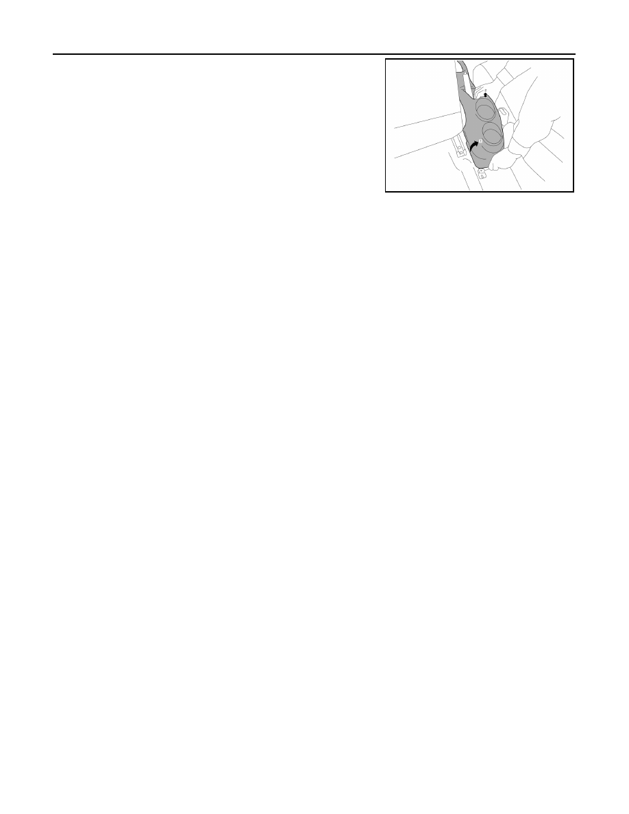
8. Raise rear right corner of center console assembly, rotating

slightly, making sure to lift assembly upward over the parking

brake handle.

9. Disconnect harness connector from power socket and harness

connector from USB/auxiliary jack (if equipped).

10. Remove center console assembly.

INSTALLATION

Installation is in the reverse order of removal.

AWJIA0695ZZ

CENTER CONSOLE LOWER

IP-25

< REMOVAL AND INSTALLATION >

C

D

E

F

G

H

I

K

L

M

A

B

IP

N

O

P

CENTER CONSOLE LOWER

Removal and Installation

INFOID:0000000009266859

REMOVAL

1. Remove center console assembly. Refer to 

IP-23, "Removal and Installation"

.

2. Remove center console lower.
a. Place front seats in a full rearward position.
b. Remove center console lower clips (A).

c. Disengage center console lower pawls and remove center con-

sole lower.

: Pawl

INSTALLATION

Installation is in the reverse order of removal.

JMJIA6052ZZ

AWJIA0706ZZ

IP-26

< UNIT DISASSEMBLY AND ASSEMBLY >

CENTER CONSOLE ASSEMBLY

UNIT DISASSEMBLY AND ASSEMBLY

CENTER CONSOLE ASSEMBLY

Exploded View

INFOID:0000000009266860

Disassembly and Assembly

INFOID:0000000009266861

DISASSEMBLY

1. Remove the center console assembly. Refer to 

IP-23, "Removal and Installation"

.

2. Remove center console support screws and center console support.
3. Remove power socket. Refer to 

PWO-6, "Removal and Installation"

.

4. Remove USB connector and auxiliary jack (if equipped). Refer to 

AV-140, "Removal and Installation"

(DISPLAY AUDIO) or 

AV-223, "Removal and Installation"

 (NAVIGATION).

ASSEMBLY

Assembly is in the reverse order of disassembly.

1.

Power socket

2.

Center console assembly

3.

Center console support

4.

USB port and auxiliary jack

AWJIA0708ZZ

LAN

LAN-1

ELECTRICAL & POWER CONTROL

C

D

E

F

G

H

I

J

K

L

B

SECTION 

LAN

A

O

P

N

CONTENTS

LAN SYSTEM

CAN FUNDAMENTAL

HOW TO USE THIS MANUAL ......................

4

HOW TO USE THIS SECTION ............................

4

Information ................................................................

4

PRECAUTION ...............................................

5

PRECAUTIONS ...................................................

5

Precautions for Trouble Diagnosis  ............................

5

Precautions for Harness Repair ................................

5

SYSTEM DESCRIPTION  ..............................

6

SYSTEM ..............................................................

6

CAN COMMUNICATION SYSTEM .............................

6

CAN COMMUNICATION SYSTEM : System De-
scription ...................................................................
..

6

DIAG ON CAN  .............................................................

6

DIAG ON CAN : System Description  ........................

6

TROUBLE DIAGNOSIS  ......................................

8

Component Description .............................................

8

Condition of Error Detection ......................................

8

Symptom When Error Occurs in CAN Communi-
cation System ..........................................................
..

9

CAN Diagnosis with CONSULT  ..............................

11

Self-Diagnosis .........................................................

12

CAN Diagnostic Support Monitor  ............................

12

How to Use CAN Communication Signal Chart  ......

14

BASIC INSPECTION  ...................................

15

DIAGNOSIS AND REPAIR WORKFLOW  .........

15

Trouble Diagnosis Flow Chart .................................

15

Trouble Diagnosis Procedure ..................................

15

CAN

HOW TO USE THIS MANUAL .....................

20

HOW TO USE THIS SECTION  .........................

20

Information ...............................................................

20

Abbreviation List ......................................................

20

PRECAUTION ..............................................

21

PRECAUTIONS .................................................

21

Precaution for Supplemental Restraint System 
(SRS) "AIR BAG" and "SEAT BELT PRE-TEN-
SIONER" .................................................................

21

Precautions for Trouble Diagnosis  ..........................

21

Precautions for Harness Repair  ..............................

21

SYSTEM DESCRIPTION  .............................

23

COMPONENT PARTS  ......................................

23

Component Parts Location  ......................................

23

SYSTEM ............................................................

24

CAN COMMUNICATION SYSTEM ............................

24

CAN COMMUNICATION SYSTEM : System De-
scription ...................................................................

24

CAN COMMUNICATION SYSTEM : CAN Com-
munication Control Circuit  .......................................

27

CAN COMMUNICATION SYSTEM : CAN System 
Specification Chart  ..................................................

28

CAN COMMUNICATION SYSTEM : CAN Com-
munication Signal Chart  ..........................................

29

WIRING DIAGRAM ......................................

31

CAN SYSTEM  ...................................................

31

Wiring Diagram ........................................................

31

BASIC INSPECTION  ...................................

36

DIAGNOSIS AND REPAIR WORKFLOW  ........

36

Interview Sheet ........................................................

36

DTC/CIRCUIT DIAGNOSIS  .........................

37

MALFUNCTION AREA CHART ........................

37


Content   ..  528  529  530  531   ..