Nissan Versa Sedan. Instruction - part 467


  Index      Nissan     Nissan Versa Sedan (2014 year) - Service and Repair Instruction


Search            copyright infringement  


Content   ..  465  466  467  468   ..


Nissan Versa Sedan. Instruction - part 467


GI-50

< BASIC INSPECTION >

SERVICE INFORMATION FOR ELECTRICAL INCIDENT

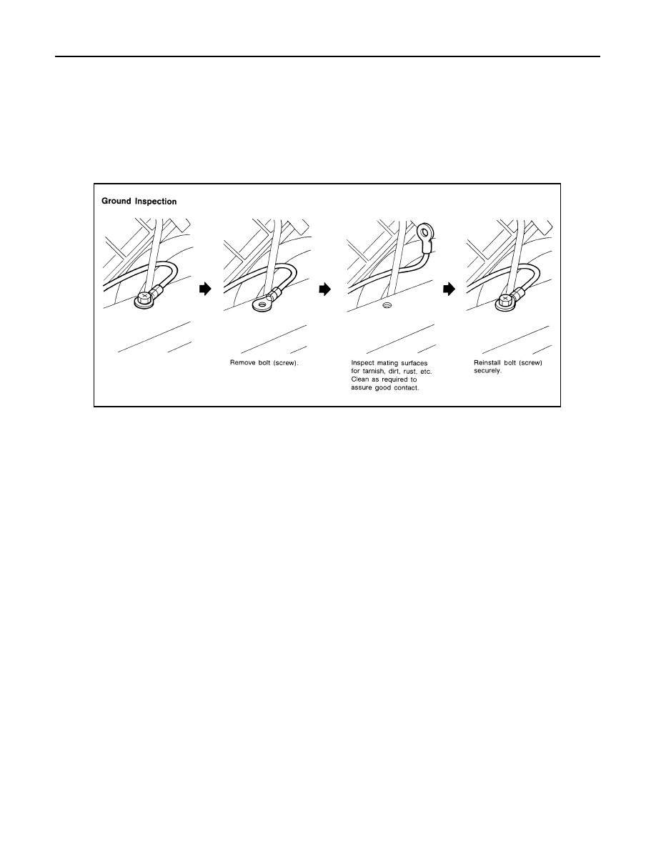
• When inspecting a ground connection follow these rules:

- Remove the ground bolt or screw.

- Inspect all mating surfaces for tarnish, dirt, rust, etc.

- Clean as required to assure good contact.

- Reinstall bolt or screw securely.

- Inspect for “add-on” accessories which may be interfering with the ground circuit.

- If several wires are crimped into one ground eyelet terminal, check for proper crimps. Make sure all of the

wires are clean, securely fastened and providing a good ground path. If multiple wires are cased in one eye-

let make sure no ground wires have excess wire insulation.

• For detailed ground distribution information, refer to “Ground Distribution” in PG section.

VOLTAGE DROP TESTS 

• Voltage drop tests are often used to find components or circuits which have excessive resistance. A voltage

drop in a circuit is caused by a resistance when the circuit is in operation.

• Check the wire in the illustration. When measuring resistance with DMM, contact by a single strand of wire

will give reading of 0 ohms. This would indicate a good circuit. When the circuit operates, this single strand

of wire is not able to carry the current. The single strand will have a high resistance to the current. This will

be picked up as a slight voltage drop. 

• Unwanted resistance can be caused by many situations as follows:

- Undersized wiring (single strand example)

- Corrosion on switch contacts

- Loose wire connections or splices.

• If repairs are needed always use wire that is of the same or larger gauge.

Measuring Voltage Drop — Accumulated Method

• Connect the DMM across the connector or part of the circuit you want to check. The positive lead of the

DMM should be closer to power and the negative lead closer to ground.

• Operate the circuit.

• The DMM will indicate how many volts are being used to “push” current through that part of the circuit.

SGI853

SERVICE INFORMATION FOR ELECTRICAL INCIDENT

GI-51

< BASIC INSPECTION >

C

D

E

F

G

H

I

J

K

L

M

B

GI

N

O

P

Note in the illustration that there is an excessive 4.1 volt drop between the battery and the bulb.

Measuring Voltage Drop — Step-by-Step

• The step-by-step method is most useful for isolating excessive drops in low voltage systems (such as those

in “Computer Controlled Systems”).

• Circuits in the “Computer Controlled System” operate on very low amperage.

• The (Computer Controlled) system operations can be adversely affected by any variation in resistance in the

system. Such resistance variation may be caused by poor connection, improper installation, improper wire

gauge or corrosion.

• The step by step voltage drop test can identify a component or wire with too much resistance.

CONTROL UNIT CIRCUIT TEST 

System Description

• When the switch is ON, the control unit lights up the lamp.

CASE 1

SGI974

SAIA0258E

MGI034A

GI-52

< BASIC INSPECTION >

SERVICE INFORMATION FOR ELECTRICAL INCIDENT

INPUT-OUTPUT VOLTAGE CHART

• The voltage value is based on the body ground.
• *: If high resistance exists in the switch side circuit (caused by a single strand), terminal 1 does not detect battery voltage. Control unit

does not detect the switch is ON even if the switch does not turn ON. Therefore, the control unit does not supply power to light up the
lamp.

CASE 2

INPUT-OUTPUT VOLTAGE CHART

• The voltage value is based on the body ground.
• *: If high resistance exists in the switch side circuit (caused by a single strand), terminal 2 does not detect approx. 0V. Control unit

does not detect the switch is ON even if the switch does not turn ON. Therefore, the control unit does not control ground to light up the
lamp.

Terminal No.

Description

Condition

Value (Approx.)

In case of high resistance such as single 
strand (V) *

+

Signal name

Input/

Output

1

Body 
ground

Switch

Input

Switch ON

Battery voltage

Lower than battery voltage Approx. 8 (Ex-
ample)

Switch OFF

0 V

Approx. 0

2

Body 
ground

Lamp

Output

Switch ON

Battery voltage

Approx. 0 (Inoperative lamp)

Switch OFF

0 V

Approx. 0

Terminal No.

Description

Condition

Value (Approx.)

In case of high resistance such as single 
strand (V) *

+

Signal name

Input/

Output

1

Body 
ground

Lamp

Output

Switch ON

0V

Battery voltage (Inoperative lamp)

Switch OFF

Battery voltage

Battery voltage

2

Body 
ground

Switch

Input

Switch ON

0 V

Higher than 0 Approx. 4 (Example)

Switch OFF

5 V

Approx. 5

MGI035A

CONSULT CHECKING SYSTEM

GI-53

< BASIC INSPECTION >

C

D

E

F

G

H

I

J

K

L

M

B

GI

N

O

P

CONSULT CHECKING SYSTEM

Description

INFOID:0000000009266910

NOTE:

This vehicle is diagnosed using the CONSULT-III plus.

• When CONSULT is connected with a data link connector equipped

on the vehicle side, it will communicate with the control unit

equipped in the vehicle and then enable various kinds of diagnos-

tic tests.

• Refer to “CONSULT-III plus Operation Instruction” for more informa-

tion.

Function and System Application

INFOID:0000000009266911

x : Applicable
1: With continuously variable transmission
2: With automatic transmission

1

: Hood release handle

2

: Data link connector

ALAIA0095ZZ

Direct Diagnostic Mode

Description

ABS

EPS

IPDM E/R

BC

M

TRANSMISSION

1

A/T

2

AIR B

A

G

MET

E

R/M

&

A

ENGINE

MUL

T

I A

V

OCCUP

ANT DETECTION

Self Diagnostic Result

The ECU self diagnostic results are displayed.

x

x

x

x

x

x

x

x

x

x

-

Data Monitor

The ECU input/output data is displayed in real time.

x

x

x

x

x

x

x

x

x

x

-

Work support

The settings for ECU functions can be changed.

x

-

-

x

x

x

-

-

x

-

x

Active Test

The ECU activates outputs to test components.

x

-

x

x

-

-

-

-

x

-

-

ECU Identification

The ECU part number is displayed.

x

x

x

x

x

x

x

-

x

x

-

DTC Work Support

The status of system monitoring tests and the self diagno-
sis status/results can be confirmed.

-

-

-

-

-

x

-

-

x

-

-

Warning History

Displays the history of the combination meter warning 
lamp indicators.

-

-

-

-

-

-

-

x

-

-

-

TROUBLE DIAG RECORD

Other results or histories, etc. that are recorded in ECU are 
displayed.

-

-

-

-

-

-

x

-

-

-

-

CAN Diagnosis

This mode displays network diagnostic results of CAN 
communication using a diagram.

x

x

x

x

x

x

x

x

x

x

-

CAN Diag Support Mntr

The result of transmit/receive diagnosis of CAN communi-
cation is displayed. 

x

x

x

x

x

x

x

x

x

x

-

Configuration

• The vehicle specification can be read and saved.
• The vehicle specification can be written when replacing 

ECU.

-

-

-

x

-

-

-

-

-

x

-

CALIB DATA

The calibration values of the ECU are displayed.

-

-

-

-

x

-

-

-

-

-

-

SRT & P-DTC Confirmation

The status of system monitoring tests and the self diagno-
sis status/results can be confirmed.

-

-

-

-

-

-

-

-

x

-

-


Content   ..  465  466  467  468   ..