Nissan Versa Sedan. Instruction - part 447
EVAP CANISTER VENT CONTROL VALVE
FL-15
< REMOVAL AND INSTALLATION >
C
D
E
F
G
H
I
J
K
L
M
A
FL
N
P
O
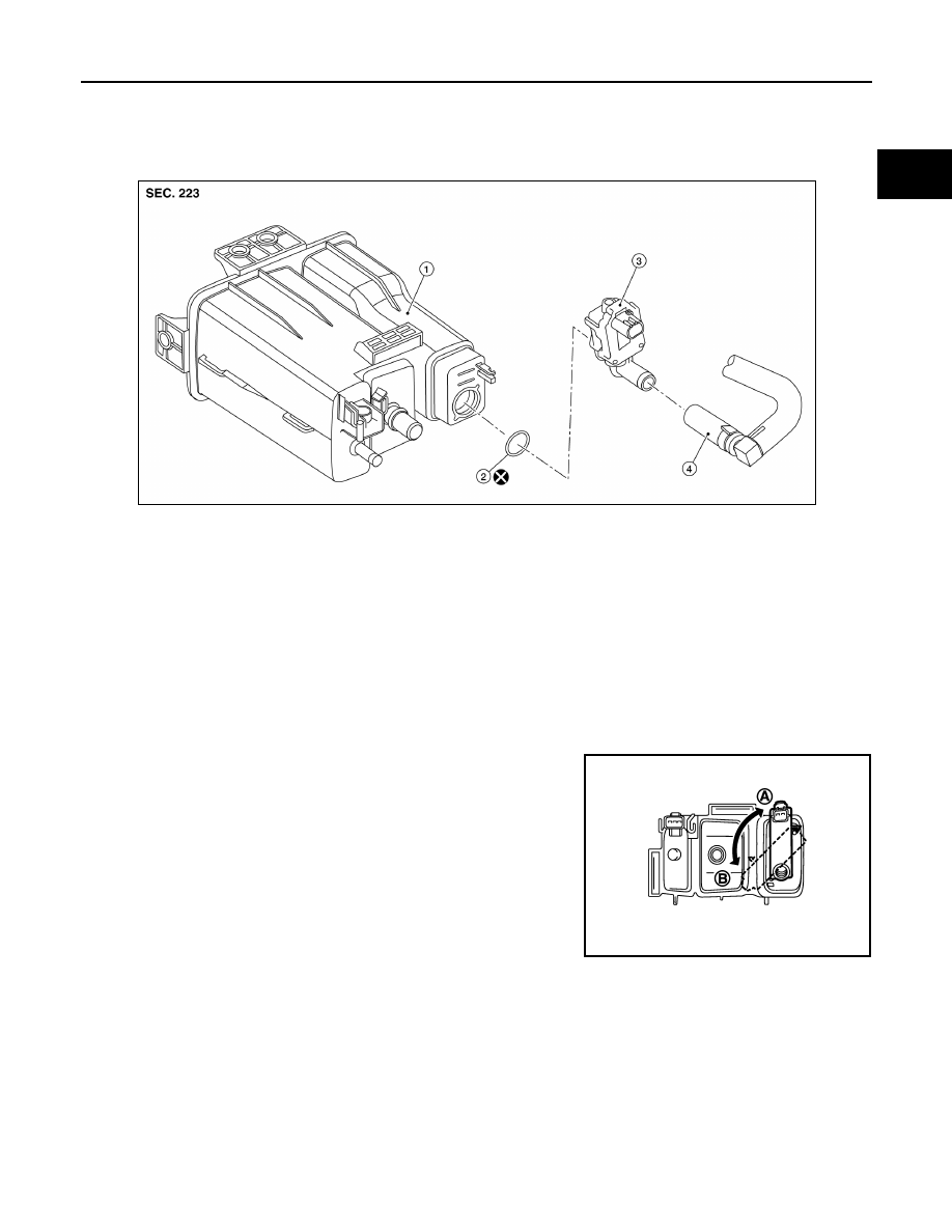
EVAP CANISTER VENT CONTROL VALVE
Exploded View
INFOID:0000000009267712
Removal and Installation
INFOID:0000000009267713
NOTE:
The EVAP canister vent control valve can be removed without removing the EVAP canister.
REMOVAL
1. Remove the EVAP canister protector cover.
2. Disconnect EVAP canister vent control valve hose from EVAP canister.
3. Disconnect the harness connector from the EVAP canister vent control valve.
4. Turn EVAP canister vent control valve counterclockwise.
5. Remove the EVAP canister vent control valve and O-ring.
CAUTION:
Do not reuse O-ring.
INSTALLATION
Installation is in the reverse order of removal.
CAUTION:
Do not reuse O-ring.
1.
EVAP canister
2.
O-ring
3.
EVAP canister vent control valve
4.
EVAP canister vent control valve hose
ALBIA0752ZZ
(A)
: Lock
(B)
: Unlock
PBIB3091E