Nissan Versa Sedan. Instruction - part 419


  Index      Nissan     Nissan Versa Sedan (2014 year) - Service and Repair Instruction


Search            copyright infringement  


Content   ..  417  418  419  420   ..


Nissan Versa Sedan. Instruction - part 419


POWER SUPPLY AND GROUND CIRCUIT

EXL-77

< DTC/CIRCUIT DIAGNOSIS >

C

D

E

F

G

H

I

J

K

M

A

B

EXL

N

O

P

Is the fuse blown?

YES

>> Replace the blown fuse or fusible link after repairing the affected circuit.

NO

>> GO TO 2

2.

 CHECK BATTERY POWER SUPPLY CIRCUIT

1. Turn ignition switch OFF.

2. Disconnect IPDM E/R.

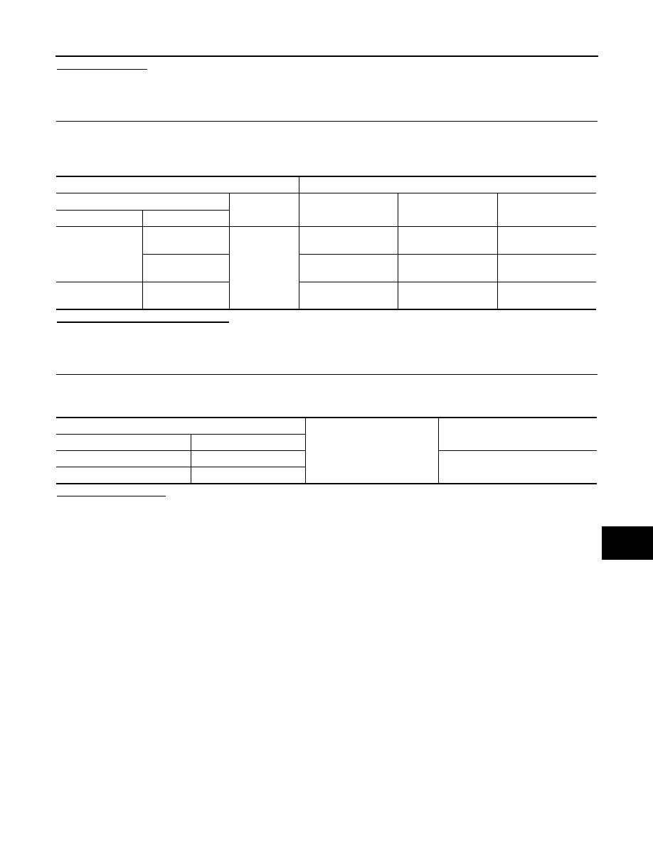
3. Check voltage between IPDM E/R connectors and ground.

Is the measurement value normal?

YES

>> GO TO 3

NO

>> Repair or replace harness.

3.

 CHECK GROUND CIRCUIT

1. Turn ignition switch OFF.

2. Check continuity between IPDM E/R connectors and ground.

Does continuity exist?

YES

>> Inspection End.

NO

>> Repair or replace harness.

Terminals

Ignition switch position

(+)

(

−)

OFF

ON

START

Connector

Terminal

E42

1

Ground

Battery
voltage

Battery
voltage

Battery
voltage

2

Battery
voltage

Battery
voltage

Battery
voltage

E44

10

0V

Battery
voltage

Battery
voltage

IPDM E/R

Ground

Continuity

Connector

Terminal

E45

19

Yes

E46

60

EXL-78

< DTC/CIRCUIT DIAGNOSIS >

HEADLAMP (HI) CIRCUIT

HEADLAMP (HI) CIRCUIT

Description

INFOID:0000000009269641

The IPDM E/R (intelligent power distribution module engine room) controls the headlamp high relay based on

inputs from the BCM via the CAN communication lines. When the headlamp high relay is energized, power

flows through fuses 34 and 35, located in the IPDM E/R. Power then flows to the front combination lamp LH

and RH high beams.

Component Function Check

INFOID:0000000009269642

1.

CHECK HEADLAMP (HI) OPERATION

WITHOUT CONSULT

1. Start IPDM E/R auto active test. Refer to 

PCS-9, "Diagnosis Description"

 (with Intelligent Key) or 

PCS-36,

"Diagnosis Description"

 (without Intelligent Key).

2. Check that the headlamp switches to the high beam.

CONSULT

1. Select EXTERNAL LAMPS of IPDM E/R active test item.

2. While operating the test items, check that the headlamp switches to the high beam.

Does the headlamp switch to high beam?

YES

>> Headlamp (HI) circuit is normal.

NO

>> Refer to 

EXL-78, "Diagnosis Procedure"

.

Diagnosis Procedure

INFOID:0000000009269643

Regarding Wiring Diagram information, refer to 

EXL-34, "Wiring Diagram"

.

1.

CHECK HEADLAMP (HI) FUSES

1. Turn the ignition switch OFF.

2. Check that the following fuses are not blown.

Is the fuse blown?

YES

>> Replace the fuse after repairing the affected circuit.

NO

>> GO TO 2.

2.

CHECK HIGH BEAM BULB

Check the applicable high beam bulb to be sure the proper bulb standard is in use and the bulb is not open.
Is the bulb OK?

YES

>> GO TO 3.

NO

>> Replace the bulb.

3.

CHECK HEADLAMP (HI) OUTPUT VOLTAGE

1. Turn the ignition switch OFF.

2. Disconnect the front combination lamp connector E25 or E26.

3. Turn the ignition switch ON.

4. Turn the high beam headlamps ON.

5. With the high beam headlamps ON, check the voltage between the combination lamp connector and

ground.

HI

: Headlamp switches to the high beam.

OFF

: Headlamp OFF

Unit

Location

Fuse No.

Capacity

Headlamp HI (LH) 

IPDM E/R

35

10A

Headlamp HI (RH) 

IPDM E/R

34

10A

HEADLAMP (HI) CIRCUIT

EXL-79

< DTC/CIRCUIT DIAGNOSIS >

C

D

E

F

G

H

I

J

K

M

A

B

EXL

N

O

P

Is the inspection result normal?

YES

>> GO TO 5.

NO

>> GO TO 4.

4.

CHECK HEADLAMP (HI) CIRCUIT FOR OPEN

1. Turn the ignition switch OFF.

2. Disconnect IPDM E/R connector E45.

3. Check continuity between the IPDM E/R harness connector E45 and the front combination lamp harness

connector E25 or E26.

Is the inspection result normal?

YES

>> Replace IPDM E/R. Refer to 

PCS-30, "Removal and Installation"

 (with Intelligent Key) or 

PCS-56,

"Removal and Installation"

 (without Intelligent Key).

NO

>> Repair or replace the harness or connector.

5.

CHECK FRONT COMBINATION LAMP (HI) GROUND CIRCUIT

Check continuity between the front combination lamp harness connector and ground.

Is the inspection result normal?

YES

>> Replace malfunctioning lamp.

NO

>> Repair or replace the harness or connector (without daytime light system).

>> GO TO 6 (with daytime light system).

6.

CHECK FRONT COMBINATION LAMP LH TO DAYTIME LIGHT RELAY 1 GROUND CIRCUIT

1. Disconnect daytime light relay 1 connector E37.

2. Check continuity between the daytime light relay 1 harness connector E37 and the front combination lamp

LH harness connector E25.

Is the inspection result normal?

YES

>> GO TO 7.

NO

>> Repair or replace the harness or connector.

7.

CHECK DAYTIME LIGHT RELAY 1 GROUND CIRCUIT

Check continuity between the daytime light relay 1 harness connector E37 and ground.

Is the inspection result normal?

YES

>> Replace daytime light relay 1.

(+)

(

−)

Voltage

Connector

Terminal

LH

E25

1

Ground

Battery voltage

RH

E26

1

Connector

Terminal

Connector

Terminal

Continuity

LH

E45

25

E25

1

Yes

RH

27

E26

1

Connector

Terminal

Continuity

LH

E25

2

Ground

Yes

RH

E26

2

Connector

Terminal

Connector

Terminal

Continuity

E37

3

E25

2

Yes

Connector

Terminal

Continuity

E37

4

Ground

Yes

EXL-80

< DTC/CIRCUIT DIAGNOSIS >

HEADLAMP (HI) CIRCUIT

NO

>> Repair or replace the harness or connector.


Content   ..  417  418  419  420   ..