Nissan Versa Sedan. Instruction - part 343
P1551, P1552 BATTERY CURRENT SENSOR
EC-371
< DTC/CIRCUIT DIAGNOSIS >
[HR16DE]
C
D
E
F
G
H
I
J
K
L
M
A
EC
N
P
O
Component Inspection
INFOID:0000000009620497
1.
CHECK BATTERY CURRENT SENSOR
1. Turn ignition switch OFF.
2. Reconnect harness connectors disconnected.
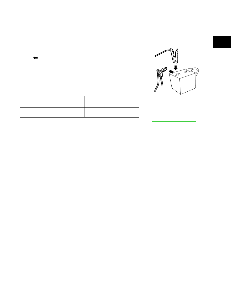
3. Disconnect battery negative cable (1).
4. Install jumper cable (A) between battery negative terminal and
body ground.
5. Turn ignition switch ON.
6. Check the voltage between ECM harness connector terminals
as per the following.
Before measuring the terminal voltage, confirm that the battery is fully charged. Refer to
.
Is the inspection result normal?
YES
>> INSPECTION END
NO
>> Replace battery negative cable assembly.
: To body ground
ECM
Voltage (V)
Connector
+
–
Terminal
Terminal
F11
58
(Battery current sensor signal)
68
Approx. 2.5
JPBIA3287ZZ