Nissan Versa Sedan. Instruction - part 326


  Index      Nissan     Nissan Versa Sedan (2014 year) - Service and Repair Instruction


Search            copyright infringement  


Content   ..  324  325  326  327   ..


Nissan Versa Sedan. Instruction - part 326


P0448 EVAP CANISTER VENT CONTROL VALVE

EC-303

< DTC/CIRCUIT DIAGNOSIS >

[HR16DE]

C

D

E

F

G

H

I

J

K

L

M

A

EC

N

P

O

Component Inspection

INFOID:0000000009620490

1.

CHECK EVAP CANISTER VENT CONTROL VALVE-I

1. Turn ignition switch OFF.

2. Remove EVAP canister vent control valve from EVAP canister.

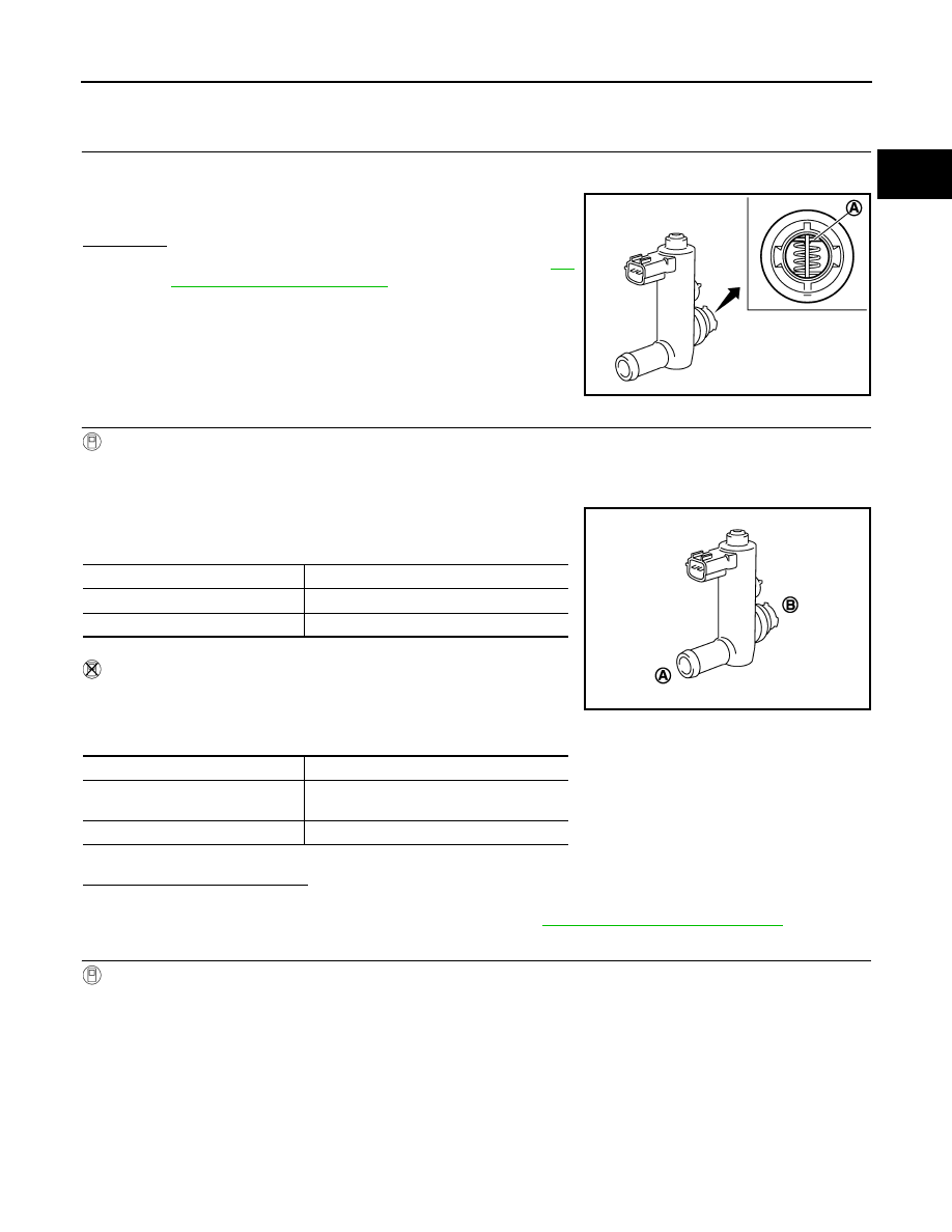
3. Check portion (A) of EVAP canister vent control valve for being

rusted.

Is it rusted?

YES

>> Replace EVAP canister vent control valve. Refer to 

FL-

15, "Removal and Installation"

.

NO

>> GO TO 2.

2.

CHECK EVAP CANISTER VENT CONTROL VALVE-II

With CONSULT

1. Reconnect harness connectors disconnected.

2. Turn ignition switch ON.

3. Perform “VENT CONTROL/V” in “ACTIVE TEST” mode of “ENGINE” using CONSULT.

4. Check air passage continuity and operation delay time.

Make sure new O-ring is installed properly.

Operation takes less than 1 second.

Without CONSULT

Check air passage continuity and operation delay time under the fol-

lowing conditions.

Make sure new O-ring is installed properly.

Operation takes less than 1 second.

Is the inspection result normal?

YES

>> GO TO 3.

NO

>> Replace EVAP canister vent control valve. Refer to 

FL-15, "Removal and Installation"

.

3.

CHECK EVAP CANISTER VENT CONTROL VALVE-III

With CONSULT

1. Clean the air passage [portion (A) to (B)] of EVAP canister vent control valve using an air blower.

2. Perform “VENT CONTROL/V” in “ACTIVE TEST” mode of “ENGINE” using CONSULT.

JMBIA0168ZZ

VENT CONT/V condition

Air passage continuity between (A) and (B)

ON

Not existed

OFF

Existed

Condition

Air passage continuity between (A) and (B)

12 V direct current supply between 
terminals (1) and (2)

Not existed

OFF

Existed

JMBIA0169ZZ

EC-304

< DTC/CIRCUIT DIAGNOSIS >

[HR16DE]

P0448 EVAP CANISTER VENT CONTROL VALVE

3. Check air passage continuity and operation delay time.

Make sure new O-ring is installed properly.

Operation takes less than 1 second.

Without CONSULT

1. Clean the air passage [portion (A) to (B)] of EVAP canister vent

control valve using an air blower.

2. Check air passage continuity and operation delay time under the

following conditions.

Make sure new O-ring is installed properly.

Operation takes less than 1 second.

Is the inspection result normal?

YES

>> INSPECTION END

NO

>> Replace EVAP canister vent control valve. Refer to 

FL-15, "Removal and Installation"

.

VENT CONT/V condition 

Air passage continuity between (A) and (B)

ON

Not existed

OFF

Existed

Condition

Air passage continuity between (A) and (B)

12 V direct current supply between
 terminals (1) and (2)

Not existed

OFF

Existed

JMBIA0169ZZ

P0451 EVAP CONTROL SYSTEM PRESSURE SENSOR

EC-305

< DTC/CIRCUIT DIAGNOSIS >

[HR16DE]

C

D

E

F

G

H

I

J

K

L

M

A

EC

N

P

O

P0451 EVAP CONTROL SYSTEM PRESSURE SENSOR

DTC Logic

INFOID:0000000009267184

DTC DETECTION LOGIC

NOTE:

If DTC P0451 is displayed with DTC P0643, first perform the trouble diagnosis for DTC P0643. Refer to

EC-344, "DTC Logic"

.

DTC CONFIRMATION PROCEDURE

1.

PRECONDITIONING

If DTC Confirmation Procedure has been previously conducted, always perform the following procedure

before conducting the next test.

1. Turn ignition switch OFF and wait at least 10 seconds.

2. Turn ignition switch ON.

3. Turn ignition switch OFF and wait at least 10 seconds.

>> GO TO 2.

2.

PERFORM DTC CONFIRMATION PROCEDURE

1. Turn ignition switch OFF and wait at least 10 seconds.

2. Start engine and wait at least 40 seconds.

NOTE:

Do not depress accelerator pedal even slightly.

3. Check 1st trip DTC.
Is 1st trip DTC detected?

YES

>> Proceed to 

EC-305, "Diagnosis Procedure"

.

NO

>> INSPECTION END

Diagnosis Procedure

INFOID:0000000009267185

1.

CHECK EVAP CONTROL SYSTEM PRESSURE SENSOR CONNECTOR FOR WATER

1. Turn ignition switch OFF.

2. Disconnect EVAP control system pressure sensor harness connector.

3. Check sensor harness connector for water.

Is the inspection result normal?

YES

>> GO TO 2.

NO

>> Repair or replace harness connector.

DTC No.

Trouble diagnosis name

(Trouble diagnosis content)

DTC detecting condition

Possible cause

P0451

EVAP SYS PRES SEN
(EVAP control system pressure 
sensor performance)

ECM detects a sloshing signal from 
the EVAP control system pressure 
sensor

• Harness or connectors

(EVAP control system pressure sensor circuit is 
shorted.)
[Crankshaft position sensor (POS) circuit is 
shorted.]
(Battery current sensor circuit is shorted.)
(Refrigerant pressure sensor circuit is shorted.)
(Accelerator pedal position sensor 2 circuit is 
shorted.)

• EVAP control system pressure sensor
• Crankshaft position sensor (POS)
• Battery current sensor
• Refrigerant pressure sensor
• Accelerator pedal position sensor

Water should not exist.

EC-306

< DTC/CIRCUIT DIAGNOSIS >

[HR16DE]

P0451 EVAP CONTROL SYSTEM PRESSURE SENSOR

2.

CHECK EVAP CONTROL SYSTEM PRESSURE SENSOR POWER SUPPLY

1. Turn ignition switch ON.

2. Check the voltage between EVAP control system pressure sensor harness connector and ground.

Is the inspection result normal?

YES

>> GO TO 6.

NO

>> GO TO 3.

3.

CHECK EVAP CONTROL SYSTEM PRESSURE SENSOR POWER SUPPLY CIRCUIT

1. Turn ignition switch OFF.

2. Disconnect ECM harness connector.

3. Check the continuity between EVAP control system pressure sensor harness connector and ECM har-

ness connector.

4. Also check harness for short to ground and to power.
Is the inspection result normal?

YES

>> GO TO 4.

NO

>> Repair or replace error-detected parts

4.

CHECK SENSOR POWER SUPPLY CIRCUIT

Check harness for short to power and short to ground, between the following terminals.

*: With A/C models
Is the inspection result normal?

YES

>> GO TO 5.

NO

>> Repair short to ground or short to power in harness or connectors.

5.

CHECK COMPONENTS

Check the following.

• Battery current sensor (Refer to 

EC-368, "Component Inspection"

).

• CKP sensor (POS) (Refer to 

EC-274, "Component Inspection"

).

• Refrigerant pressure sensor (Refer to 

EC-448, "Component Function Check"

).

• Accelerator pedal position sensor (Refer to 

EC-410, "Component Inspection"

).

Is the inspection result normal?

YES

>> Check intermittent incident. Refer to 

GI-45, "Intermittent Incident"

.

NO

>> Replace malfunctioning component.

6.

CHECK EVAP CONTROL SYSTEM PRESSURE SENSOR GROUND CIRCUIT

EVAP control system pressure sensor

Ground

Voltage

(Approx.)

Connector

Terminal

B3

3

Ground

5 V

EVAP control system pressure sensor

ECM

Continuity

Connector

Terminal

Connector

Terminal

B3

3

F11

71

Existed

ECM

Sensor

Connector

Terminal

Name

Connector

Terminal

F11

71

EVAP control system pressure sen-
sor

B3

3

Battery current sensor

F9

1

75

CKP sensor (POS)

F15

1

E16

101

Refrigerant pressure sensor

*

E17

3

102

Accelerator pedal position sensor 2

E12

5


Content   ..  324  325  326  327   ..