Nissan Versa Sedan. Instruction - part 318
P0327, P0328 KS
EC-271
< DTC/CIRCUIT DIAGNOSIS >
[HR16DE]
C
D
E
F
G
H
I
J
K
L
M
A
EC
N
P
O
2. Also check harness for short to ground and short to power.
Is the inspection result normal?
YES
>> GO TO 4.
NO
>> Repair open circuit or short to ground or short to power in harness or connectors.
4.
CHECK KNOCK SENSOR
EC-271, "Component Inspection"
Is the inspection result normal?
YES
>> GO TO 5.
NO
>> Replace knock sensor. Refer to
.
5.
CHECK INTERMITTENT INCIDENT
GI-45, "Intermittent Incident"
.
>> INSPECTION END
Component Inspection
INFOID:0000000009267155
1.
CHECK KNOCK SENSOR
1. Turn ignition switch OFF.
2. Disconnect knock sensor harness connector.
3. Check resistance between knock sensor terminals as follows.
NOTE:
It is necessary to use an ohmmeter which can measure more than 10 M
Ω.
CAUTION:
Do not use any knock sensors that have been dropped or physically damaged. Use only new ones.
Is the inspection result normal?
YES
>> INSPECTION END
NO
>> Replace knock sensor. Refer to
.
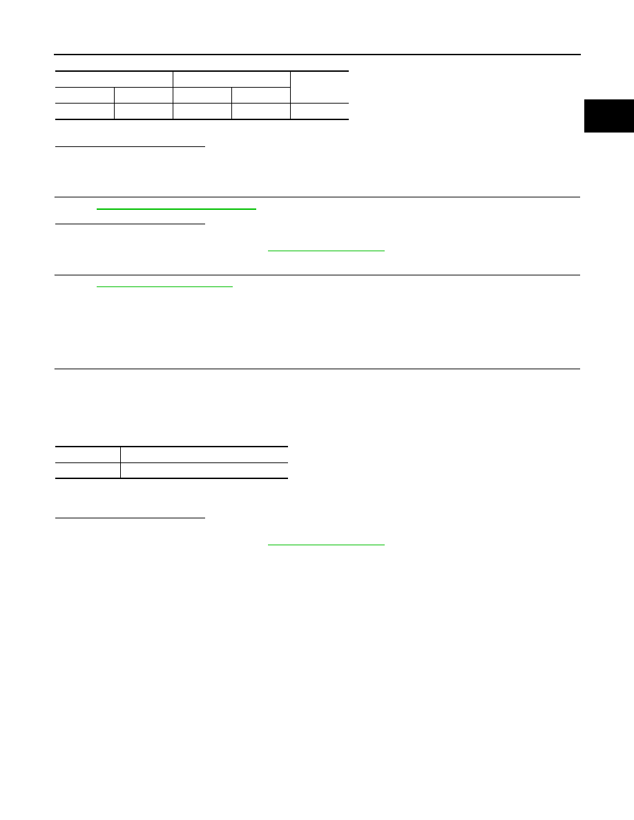
Knock sensor
ECM
Continuity
Connector
Terminal
Connector
Terminal
F14
1
F11
37
Existed
Terminals
Resistance [at 20
°C (68°F)]
1 and 2
Approx. 532 - 588 k
Ω