Nissan Versa Sedan. Instruction - part 290
U1001 CAN COMM CIRCUIT
EC-159
< DTC/CIRCUIT DIAGNOSIS >
[HR16DE]
C
D
E
F
G
H
I
J
K
L
M
A
EC
N
P
O
U1001 CAN COMM CIRCUIT
Description
INFOID:0000000009619956
CAN (Controller Area Network) is a serial communication line for real time application. It is an on-vehicle mul-
tiplex communication line with high data communication speed and excellent error detection ability. Many elec-
tronic control units are equipped onto a vehicle, and each control unit shares information and links with other
control units during operation (not independent). In CAN communication, control units are connected with 2
communication lines (CAN H line, CAN L line) allowing a high rate of information transmission with less wiring.
Each control unit transmits/receives data but selectively reads required data only.
DTC Logic
INFOID:0000000009267057
DTC DETECTION LOGIC
DTC CONFIRMATION PROCEDURE
1.
PERFORM DTC CONFIRMATION PROCEDURE
1. Turn ignition switch ON and wait at least 3 seconds.
2. Check DTC.
Is DTC detected?
YES
>>
.
NO
>> INSPECTION END
Diagnosis Procedure
INFOID:0000000009267058
Go to
LAN-15, "Trouble Diagnosis Flow Chart"
.
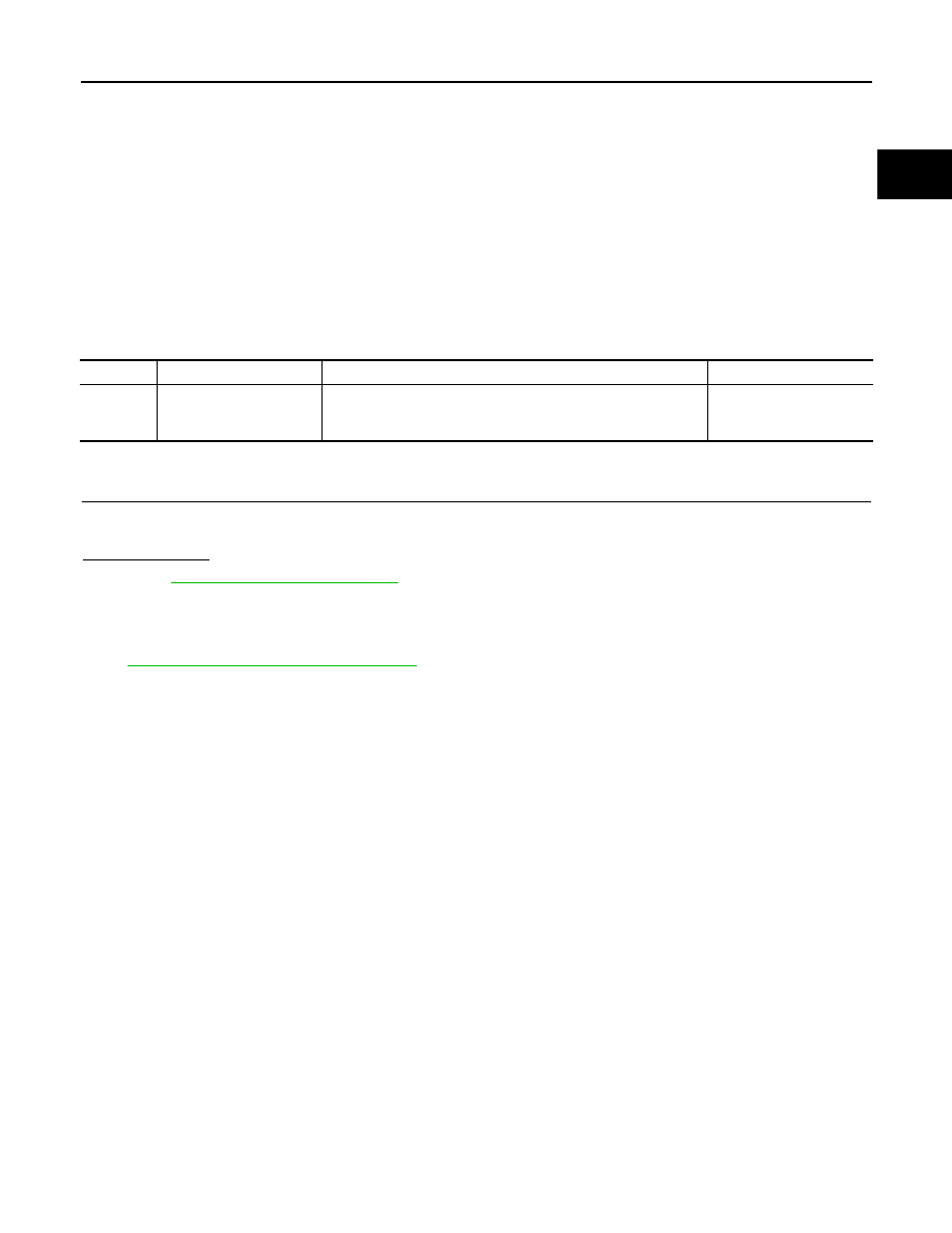
DTC No.
Trouble diagnosis name
DTC detecting condition
Possible cause
U1001
CAN communication line
When ECM is not transmitting or receiving CAN communication
signal other than OBD (emission related diagnosis) for 2 seconds
or more.
Harness or connectors
(CAN communication line
is open or shorted)