Nissan Versa Sedan. Instruction - part 283
BASIC INSPECTION
EC-131
< BASIC INSPECTION >
[HR16DE]
C
D
E
F
G
H
I
J
K
L
M
A
EC
N
P
O
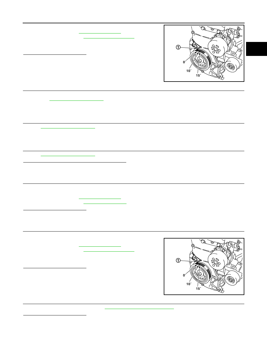
2. Check ignition timing with a timing light.
For procedure, refer to
.
For specification, refer to
-
Timing indicator (1)
Is the inspection result normal?
YES
>> GO TO 19.
NO
>> GO TO 11.
11.
PERFORM ACCELERATOR PEDAL RELEASED POSITION LEARNING
1. Stop engine.
2. Perform
.
>> GO TO 12.
12.
PERFORM THROTTLE VALVE CLOSED POSITION LEARNING
Perform
>> GO TO 13.
13.
PERFORM IDLE AIR VOLUME LEARNING
Perform
Is idle air volume learning carried out successfully?
YES
>> GO TO 14.
NO
>> Follow the instruction of IDLE AIR VOLUME LEARNING. Then GO TO 4.
14.
CHECK TARGET IDLE SPEED AGAIN
1. Start engine and warm it up to normal operating temperature.
2. Check idle speed.
For procedure, refer to
.
For specification, refer to
Is the inspection result normal?
YES
>> GO TO 15.
NO
>> GO TO 17.
15.
CHECK IGNITION TIMING AGAIN
1. Run engine at idle.
2. Check ignition timing with a timing light.
For procedure, refer to
.
For specification, refer to
-
Timing indicator (1)
Is the inspection result normal?
YES
>> GO TO 19.
NO
>> GO TO 16.
16.
CHECK TIMING CHAIN INSTALLATION
Check timing chain installation. Refer to
EM-47, "Removal and Installation"
Is the inspection result normal?
YES
>> GO TO 17.
NO
>> Repair the timing chain installation. Then GO TO 4.
MBIB1331E
MBIB1331E