Nissan Versa Sedan. Instruction - part 239
DLK-274
< REMOVAL AND INSTALLATION >
[WITHOUT INTELLIGENT KEY SYSTEM]
HOOD
REMOVAL AND INSTALLATION
HOOD
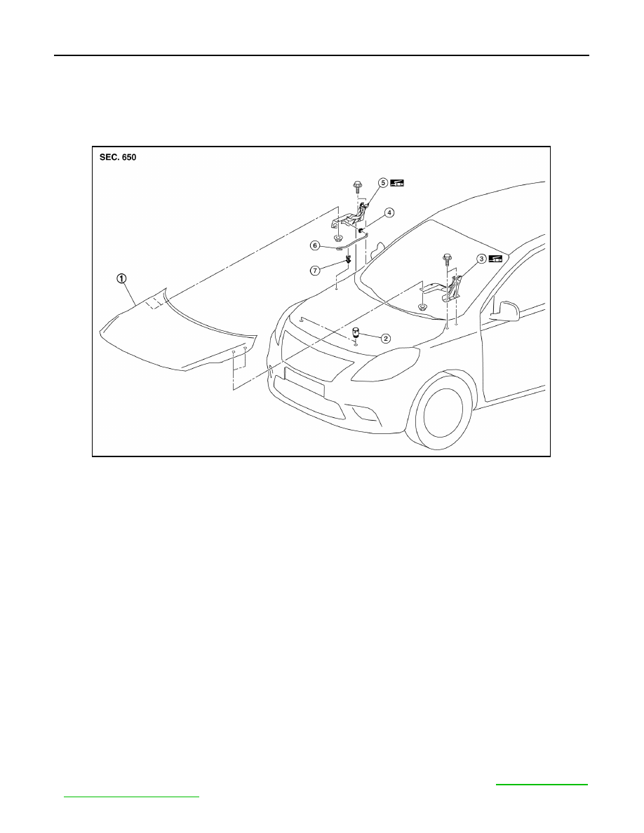
Exploded View
INFOID:0000000009268975
HOOD ASSEMBLY
HOOD ASSEMBLY : Removal and Installation
INFOID:0000000009268976
CAUTION:
• Use two people when removing or installing hood assembly due to its heavy weight.
• Use protective tape or shop cloths to protect surrounding components from damage during removal
and installation of hood assembly.
REMOVAL
1. Support hood assembly using a suitable tool.
WARNING:
Bodily injury may occur if hood assembly is not supported properly when removing hood assem-
bly.
2. Remove hood hinge to hood nuts and then remove the hood assembly.
CAUTION:
Use two people when removing or installing hood assembly due to its heavy weight.
INSTALLATION
Installation is in the reverse order of removal.
CAUTION:
• After installation, perform the hood assembly adjustment procedure. Refer to
.
1.
Hood assembly
2.
Hood bumper rubber
3.
Hood hinge (LH)
4.
Grommet
5.
Hood hinge (RH)
6.
Hood support rod
7.
Clamp
AWKIA1877ZZ