Nissan Versa Sedan. Instruction - part 195
DLK-98
< DTC/CIRCUIT DIAGNOSIS >
[WITH INTELLIGENT KEY SYSTEM]
REMOTE KEYLESS ENTRY RECEIVER
Is the inspection result normal?
YES
>> Reconnect BCM, GO TO 4
NO
>> Repair or replace harness between BCM and remote keyless entry receiver.
4.
CHECK REMOTE KEYLESS ENTRY RECEIVER GROUND CIRCUIT
Check continuity between remote keyless entry receiver connector and ground.
Is the inspection result normal?
YES
>> GO TO 6
NO
>> GO TO 5
5.
CHECK REMOTE KEYLESS ENTRY RECEIVER CIRCUIT 2
Check continuity between BCM connector and remote keyless entry receiver connector.
Is the inspection result normal?
YES
>> GO TO 6
NO
>> Repair or replace harness between BCM and remote keyless entry receiver.
6.
CHECK REMOTE KEYLESS ENTRY RECEIVER CIRCUIT 3
1. Check continuity between BCM connector and remote keyless entry receiver connector.
2. Check continuity between BCM connector and ground.
Is the inspection result normal?
YES
>> GO TO 7
NO
>> Repair or replace harness between BCM and remote keyless entry.
7.
CHECK REMOTE KEYLESS ENTRY RECEIVER RSSI SIGNAL CIRCUIT
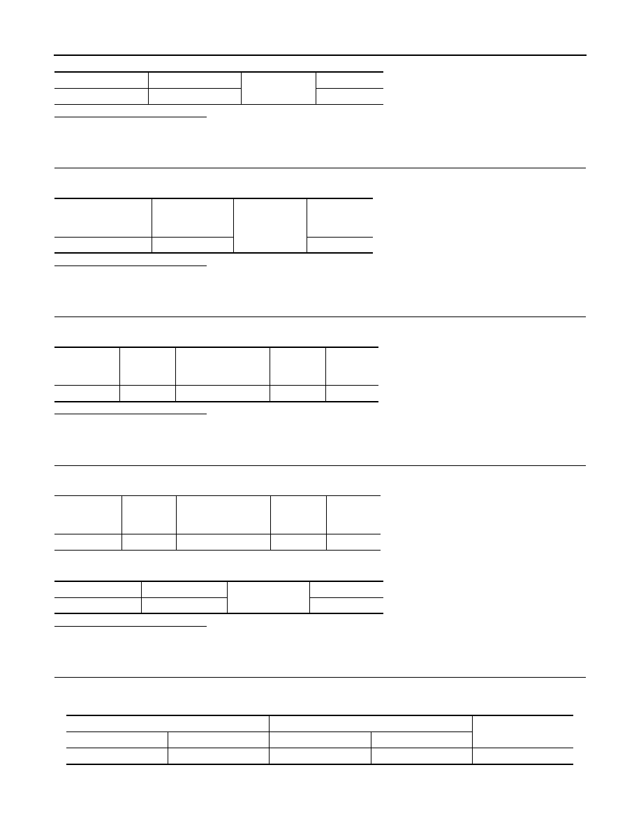
1. Disconnect BCM connector.
2. Check continuity between BCM harness connector and remote keyless entry receiver harness connector.
3. Check continuity between BCM harness connector and ground.
BCM connector
Terminal
Ground
Continuity
M97
19
No
Remote keyless entry
receiver
connector
Terminal
Ground
Continuity
M90
1
Yes
BCM
connector
Terminal
Remote keyless entry
receiver
connector
Terminal
Continuity
M97
18
M90
1
Yes
BCM
connector
Terminal
Remote keyless entry
receiver
connector
Terminal
Continuity
M97
20
M90
2
Yes
BCM connector
Terminal
Ground
Continuity
M97
20
No
BCM
Remote keyless entry receiver
Continuity
Connector
Terminal
Connector
Terminal
M97
22
M90
3
Yes