Nissan Versa Sedan. Instruction - part 149
CHG
CHARGING SYSTEM
CHG-27
< SYMPTOM DIAGNOSIS >
C
D
E
F
G
H
I
J
K
L
B
A
O
P
N
SYMPTOM DIAGNOSIS
CHARGING SYSTEM
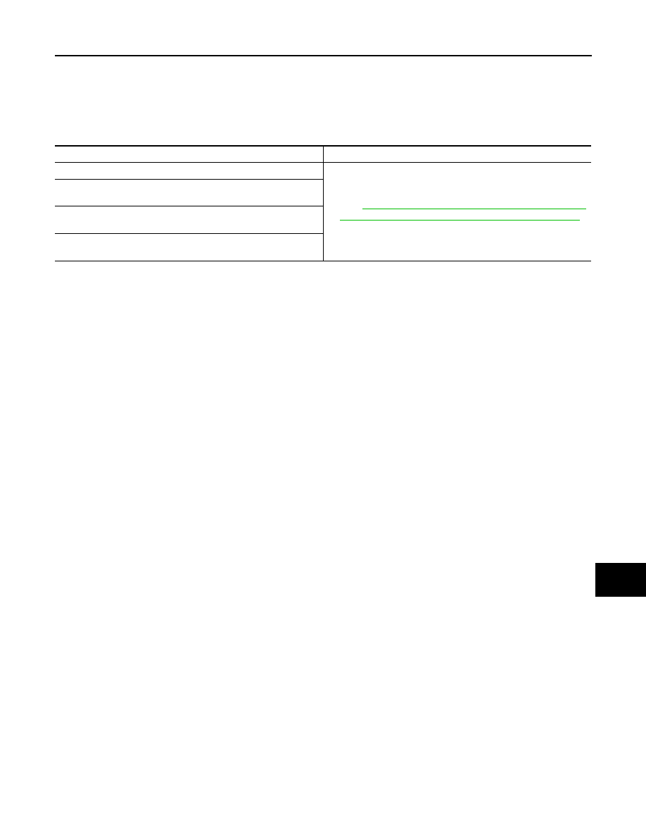
Symptom Table
INFOID:0000000009269537
Symptom
Reference
Battery discharged
Refer to
CHG-13, "Work Flow (With EXP-800 NI or GR8-1200 NI)"
or
CHG-16, "Work Flow (Without EXP-800 NI or GR8-1200 NI)"
The charge warning lamp does not illuminate when the ignition
switch is set to ON.
The charge warning lamp does not turn OFF after the engine
starts.
The charging warning lamp turns ON when increasing the engine
speed.