Nissan Versa Sedan. Instruction - part 96
BR-22
< REMOVAL AND INSTALLATION >
BRAKE PIPING
FRONT : Hydraulic Piping
INFOID:0000000009267537
CAUTION:
• All hoses and piping (tubes) must be free from excessive bending, twisting and pulling.
• Make sure there is no interference with other parts when turning steering both clockwise and coun-
terclockwise.
• The brake piping is an important safety part. If a brake fluid leak is detected, always disassemble the
parts. Replace applicable part with a new one, if necessary.
• Be careful not to splash brake fluid on painted areas; it may cause paint damage. If brake fluid is
splashed on painted areas, wash it away with water immediately.
• Do not bend or twist brake hose sharply, or strongly pull it.
• When removing components, cover connections so that no dirt, dust, or other foreign matter gets in.
• Do not reuse drained brake fluid.
• After installation of the ABS actuator and electric unit (control unit), refill brake system with new
brake fluid. Then bleed the air from the system. Refer to
BR-12, "Bleeding Brake System"
.
FRONT : Removal and Installation
INFOID:0000000009267538
NOTE:
When removing components such as hoses, tubes/lines, etc., cap or plug openings to prevent fluid from spill-
ing.
1.
Master cylinder brake pipe assembly
(front)
2.
Master cylinder brake pipe assembly
(rear)
3.
ABS actuator to connector brake
pipe assembly (RH)
4.
ABS actuator to connector brake
pipe assembly (LH)
5.
Brake pipe connector
6.
Brake pipe assembly (RH front)
7.
Brake pipe assembly (LH front)
8.
Master cylinder assembly
9.
Brake booster
10. ABS actuator and electric unit (con-
trol unit)
11. Lock plate
12. Front brake hose
13. Copper sealing washer
A.
To front brake hose
B.
To rear brake pipe
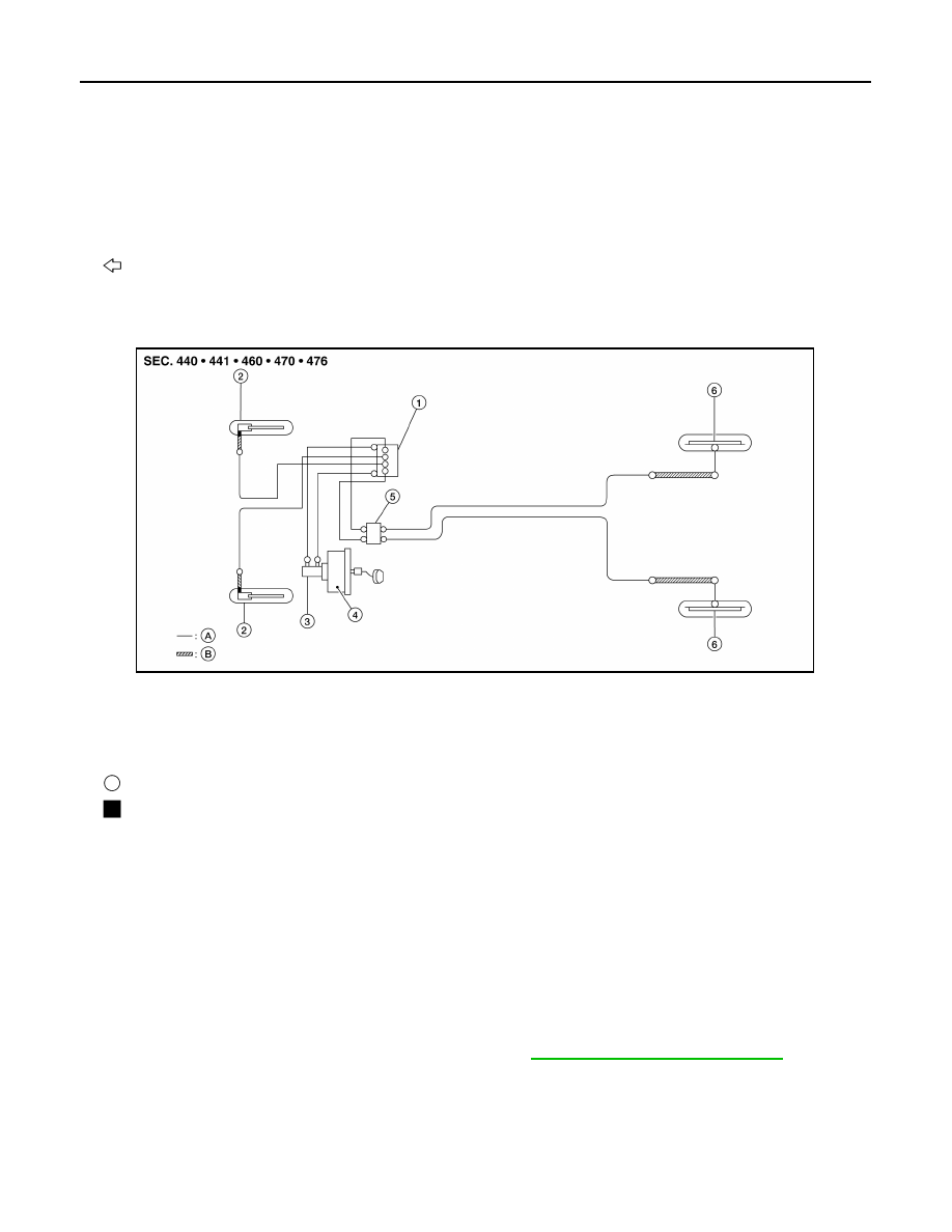
Front
1.
ABS actuator and electric unit (con-
trol unit)
2.
Front disc brake
3.
Master cylinder assembly
4.
Brake booster
5.
Connector
6.
Rear drum brake
A.
Brake pipe
B.
Brake hose
: Flare nut
: Union bolt
AWFIA0818GB
2014 Versa Sedan