Nissan Versa Sedan. Instruction - part 78


  Index      Nissan     Nissan Versa Sedan (2014 year) - Service and Repair Instruction


Search            copyright infringement  


Content   ..  76  77  78  79   ..


Nissan Versa Sedan. Instruction - part 78


BCS

COMPONENT PARTS

BCS-73

< SYSTEM DESCRIPTION >

[WITHOUT INTELLIGENT KEY SYSTEM]

C

D

E

F

G

H

I

J

K

L

B

A

O

P

N

POWER CONSUMPTION CONTROL SYSTEM
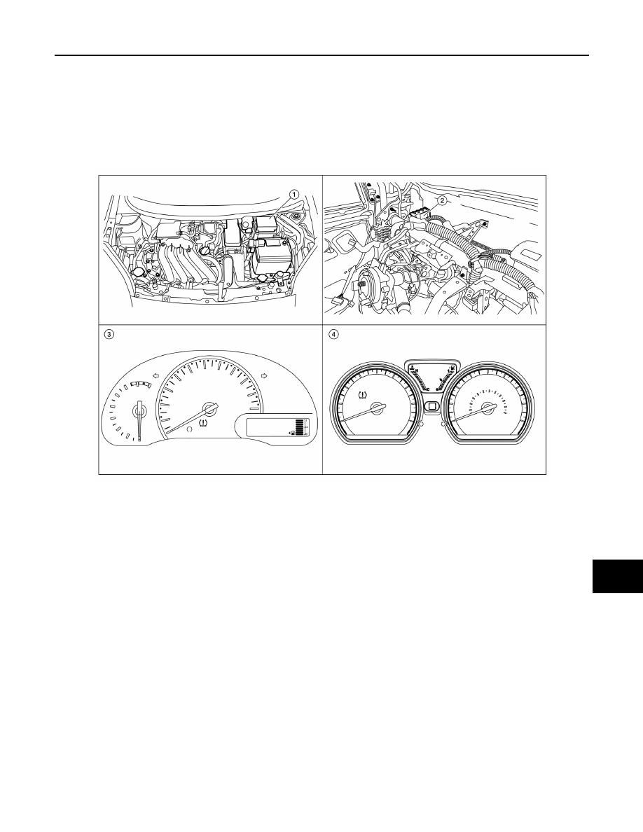
POWER CONSUMPTION CONTROL SYSTEM : Component Parts Location

INFOID:0000000009268661

1.

BCM (view with combination meter 
removed)

2.

Combination switch (lighting and 
turn signal)

3.

Combination switch (wiper and 
washer)

1

IPDM E/R

2

BCM (view with instrument panel re-
moved)

3

Combination meter (type A)

4

Combination meter (type B)

ALMIA0535ZZ

BCS-74

< SYSTEM DESCRIPTION >

[WITHOUT INTELLIGENT KEY SYSTEM]

SYSTEM

SYSTEM

BODY CONTROL SYSTEM
BODY CONTROL SYSTEM : System Description

INFOID:0000000009268662

OUTLINE

• BCM (Body Control Module) controls various electrical components. It receives the information required

from CAN communication and the signals received from each switch and sensor.

• BCM has a combination switch reading function for reading the status of combination switch (light, turn sig-

nal, wiper and washer) in addition to functions for controlling the operation of various electrical components.

It also has a signal transmission function for other systems, and a power consumption control function that

reduces the power consumption with the ignition switch OFF.

• BCM is equipped with a diagnosis function that operates with CONSULT and allows for various settings to

be changed.

BCM FUNCTION LIST

COMBINATION SWITCH READING SYSTEM

System

Reference page

Combination switch reading system

BCS-75, "COMBINATION SWITCH READING SYSTEM : System 
Diagram"

Signal buffer system

BCS-78, "SIGNAL BUFFER : System Diagram"

Power consumption control system

BCS-78, "POWER CONSUMPTION CONTROL SYSTEM : System 
Diagram"

Headlamp system

EXL-8, "HEADLAMP SYSTEM : System Diagram"

Daytime running light system

EXL-9, "WITH DAYTIME LIGHT SYSTEM : System Diagram"

Turn signal and hazard warning lamp system

EXL-10, "TURN SIGNAL AND HAZARD WARNING LAMP SYS-
TEM : System Diagram"

Parking, license plate, side maker and tail lamps system

EXL-10, "PARKING, LICENSE PLATE AND TAIL LAMP SYSTEM : 
System Diagram"

Exterior lamp battery saver system

EXL-8, "HEADLAMP SYSTEM : System Description"

Interior room lamp control system

INL-8, "INTERIOR ROOM LAMP CONTROL SYSTEM : System Di-
agram"

Interior room lamp battery saver system

INL-9, "INTERIOR ROOM LAMP CONTROL SYSTEM : System De-
scription"

Front wiper and washer system

WW-6, "System Diagram"

Instruction air conditioner system

HAC-10, "MANUAL AIR CONDITIONING SYSTEM : System Dia-
gram"

Warning chime system

WCS-7, "WARNING CHIME SYSTEM : System Diagram"

Power door lock system

DLK-200, "POWER DOOR LOCK SYSTEM : System Diagram"

Nissan vehicle immobilizer system-NATS (NVIS)

SEC-111, "NISSAN VEHICLE IMMOBILIZER SYSTEM-NATS : Sys-
tem Diagram"

Panic alarm

DLK-201, "REMOTE KEYLESS ENTRY SYSTEM : System Dia-
gram"

Rear window defogger system

DEF-5, "System Diagram"

Remote keyless entry system

DLK-201, "REMOTE KEYLESS ENTRY SYSTEM : System Dia-
gram"

Power window system

PWC-8, "System Diagram"

BCS

SYSTEM

BCS-75

< SYSTEM DESCRIPTION >

[WITHOUT INTELLIGENT KEY SYSTEM]

C

D

E

F

G

H

I

J

K

L

B

A

O

P

N

COMBINATION SWITCH READING SYSTEM : System Diagram

INFOID:0000000009268663

COMBINATION SWITCH READING SYSTEM : System Description

INFOID:0000000009268664

OUTLINE

• BCM reads the status of the combination switch (light, turn signal, wiper and washer) and recognizes the

status of each switch.

• BCM has a combination of 5 output terminals (OUTPUT 1 - 5) and 5 input terminals (INPUT 1 - 5). It reads a

maximum of 20 switch states.

COMBINATION SWITCH MATRIX

Combination switch circuit

Combination switch INPUT-OUTPUT system list

COMBINATION SWITCH READING FUNCTION

AWMIA1339GB

System

INPUT 1

INPUT 2

INPUT 3

INPUT 4

INPUT 5

OUTPUT 1

FR WASHER

FR WIPER LOW

TURN LH

TURN RH

OUTPUT 2

FR WIPER HI

FR WIPER INT

PASSING

HEADLAMP 1

OUTPUT 3

HEADLAMP 2

HI BEAM

OUTPUT  4

TAIL  LAMP

OUTPUT  5

AWMIA1340GB

BCS-76

< SYSTEM DESCRIPTION >

[WITHOUT INTELLIGENT KEY SYSTEM]

SYSTEM

Description

• BCM reads the status of the combination switch at 10 ms intervals normally.

NOTE:

BCM reads the status of the combination switch at 60 ms intervals when BCM is controlled at low power

consumption control mode.

• BCM operates as follows and judges the status of the combination switch.

- It operates the transistor on OUTPUT side in the following order: OUTPUT 1 

→ 2 → 3 → 4 → 5, and outputs

voltage waveform.

- The voltage waveform of OUTPUT corresponding to the formed circuit is input into the interface on INPUT

side if any (1 or more) switches are ON.

- It reads this change of the voltage as the status signal of the combination switch.

Operation Example

In the following operation example, the combination of the status signals of the combination switch is replaced

as follows: INPUT 1 - 5 to “1 - 5” and OUTPUT 1 - 5 to “A - E”.

Example 1: When a switch (TAIL LAMP) is turned ON

JPMIA0609GB

JMMIA0326GB


Content   ..  76  77  78  79   ..