Nissan Versa Sedan. Instruction - part 53


  Index      Nissan     Nissan Versa Sedan (2014 year) - Service and Repair Instruction


Search            copyright infringement  


Content   ..  51  52  53  54   ..


Nissan Versa Sedan. Instruction - part 53


AV-204

< DTC/CIRCUIT DIAGNOSIS >

[NAVIGATION]

MICROPHONE SIGNAL CIRCUIT

MICROPHONE SIGNAL CIRCUIT

Diagnosis Procedure

INFOID:0000000009375187

Regarding Wiring Diagram information, refer to 

AV-162, "Wiring Diagram"

.

1.

CHECK MICROPHONE SIGNAL CIRCUIT CONTINUITY

1. Turn ignition switch OFF.

2. Disconnect AV control unit connector M71 and microphone connector R15.

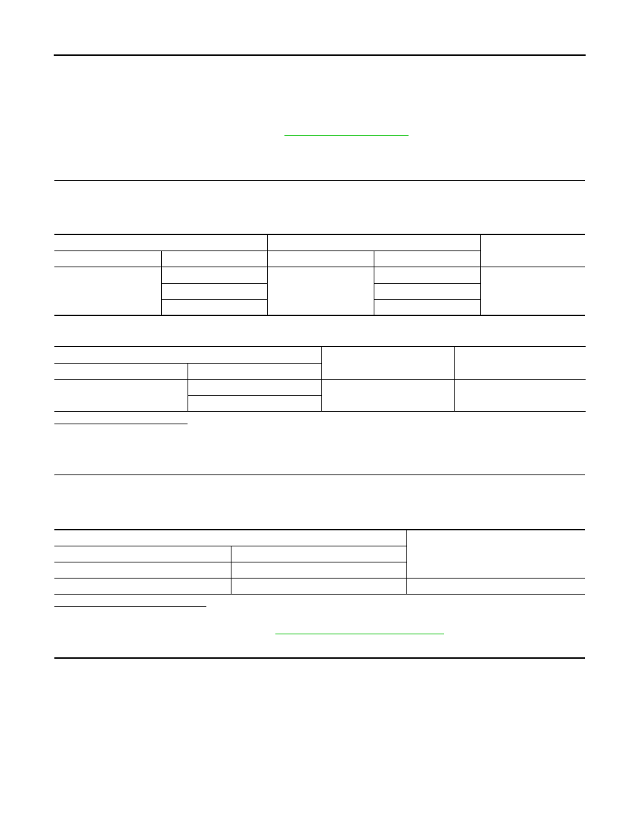
3. Check continuity between AV control unit connector M71 and microphone connector R15.

4. Check continuity between AV control unit connector M71 and ground.

Is inspection result normal?

YES

>> GO TO 2.

NO

>> Repair or replace harness or connectors.

2.

CHECK MICROPHONE VCC VOLTAGE

1. Connect AV control unit connector M71.

2. Turn ignition switch ON.

3. Check voltage between terminals of AV control unit connector M71.

Is the inspection result normal?

YES

>> GO TO 3.

NO

>> Replace AV control unit. Refer to 

AV-222, "Removal and Installation"

.

3.

CHECK MICROPHONE SIGNAL 

1. Connect microphone connector.

2. Check signal between terminals of AV control unit connector M71.

AV control unit

Microphone

Continuity

Connector

Terminal

Connector

Terminal

M71

41

R15

2

Yes

42

4

43

1

AV control unit

Ground

Continuity

Connector

Terminal

M71

42

No

43

AV control unit connector M71

Voltage

(Approx.)

(+)

(

−)

Terminal

Terminal

42

41

5.0 V

AV

MICROPHONE SIGNAL CIRCUIT

AV-205

< DTC/CIRCUIT DIAGNOSIS >

[NAVIGATION]

C

D

E

F

G

H

I

J

K

L

M

B

A

O

P

Is the inspection result normal?

YES

>> Replace AV control unit. Refer to 

AV-222, "Removal and Installation"

.

NO

>> Replace microphone. Refer to 

AV-228, "Removal and Installation"

.

AV control unit connector M71

Condition

Reference value

(+)

(

−)

Terminal

Terminal

43

41

Speak into microphone.

PKIB5037J

AV-206

< DTC/CIRCUIT DIAGNOSIS >

[NAVIGATION]

STEERING SWITCH

STEERING SWITCH

Diagnosis Procedure

INFOID:0000000009375188

Regarding Wiring Diagram information, refer to 

AV-162, "Wiring Diagram"

.

1.

CHECK STEERING WHEEL AUDIO CONTROL SWITCH RESISTANCE

1. Turn ignition switch OFF.

2. Disconnect combination switch connector M88.

3. Check resistance between the terminals of combination switch connector M88.

Is the inspection result normal?

YES

>> GO TO 2.

NO

>> Replace steering switches. Refer to 

AV-227, "Removal and Installation"

.

2.

CHECK COMBINATION SWITCH

Check continuity between combination switch connectors M88 and M30.

Is the inspection result normal?

YES

>> GO TO 3.

NO

>> Replace spiral cable. Refer to 

SR-14, "Removal and Installation"

.

3.

CHECK HARNESS BETWEEN COMBINATION SWITCH AND AV CONTROL UNIT 

1. Disconnect AV control unit connector M30.

2. Check continuity between combination switch connector M30 and AV control unit connector M70.

Combination switch connector M88

Condition

Resistance 

(Approx.)

Terminal

Terminal

14

17

Depress SOURCE switch.

1

Depress  

switch.

121

Depress  

switch.

321

Depress  

switch.

723

15

Depress  

switch.

1

Depress  

switch.

121

Depress  

switch. 

321

Combination switch 

Continuity

Connector

Terminal

Connector

Terminal

M88

14

M30

24

Yes

15

31

17

33

Combination switch

AV control unit 

Continuity

Connector

Terminal

Connector

Terminal

M30

24

M70

6

Yes

31

16

33

15

AV

STEERING SWITCH

AV-207

< DTC/CIRCUIT DIAGNOSIS >

[NAVIGATION]

C

D

E

F

G

H

I

J

K

L

M

B

A

O

P

3. Check continuity between combination switch connector M30 and ground.

Is the inspection result normal?

YES

>> Replace AV control unit. Refer to 

AV-222, "Removal and Installation"

.

NO

>> Repair or replace harness or connectors.

Combination switch

Ground

Continuity

Connector

Terminal

M30

24

No

31

33


Content   ..  51  52  53  54   ..