Nissan Versa Sedan. Instruction - part 38


  Index      Nissan     Nissan Versa Sedan (2014 year) - Service and Repair Instruction


Search            copyright infringement  


Content   ..  36  37  38  39   ..


Nissan Versa Sedan. Instruction - part 38


AV-144

< REMOVAL AND INSTALLATION >

[DISPLAY AUDIO]

MICROPHONE

MICROPHONE

Removal and Installation

INFOID:0000000009375257

REMOVAL

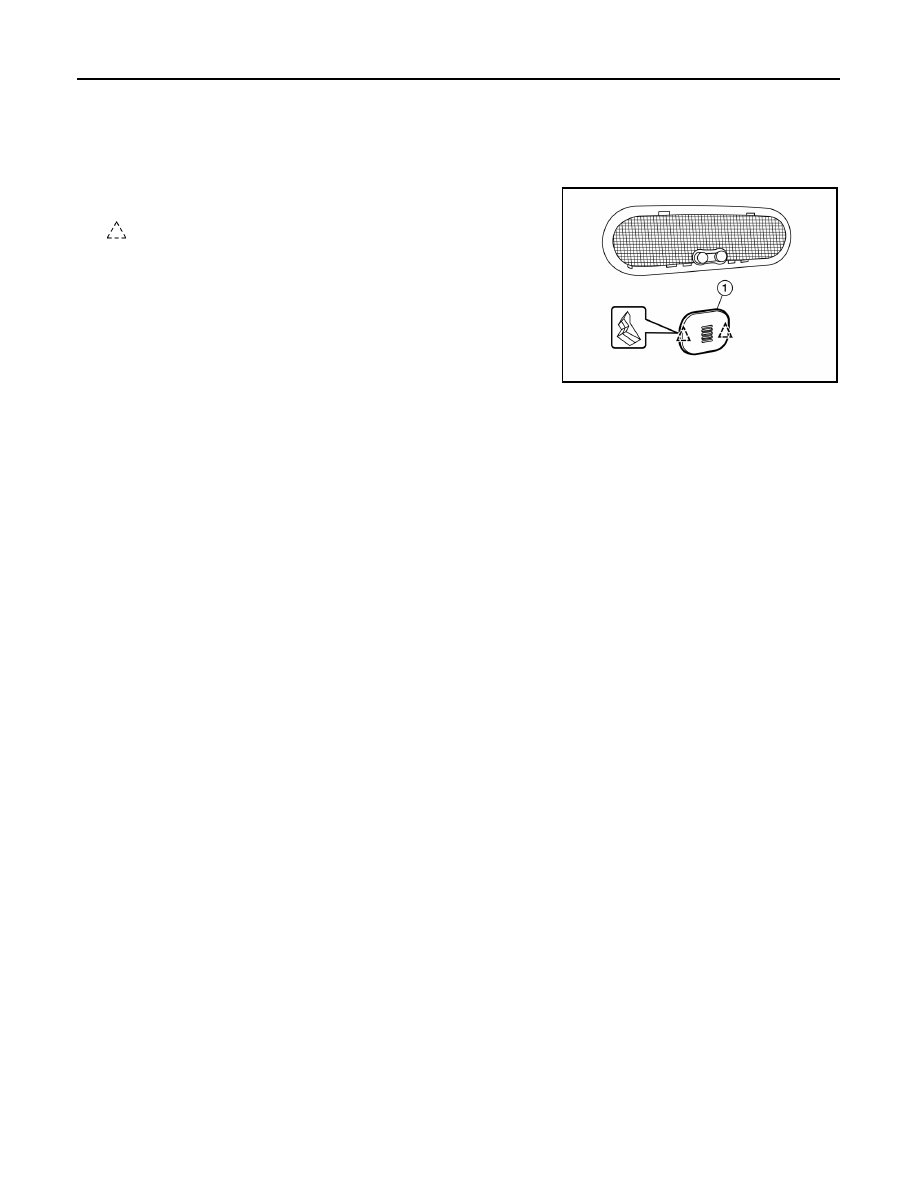
1. Remove the microphone (1) from the headlining using a suitable

tool. 

: Clip

2. Disconnect the harness connector from microphone and remove.

INSTALLATION

Installation is in the reverse order of removal.

ALNIA1306ZZ

AV

ANTENNA FEEDER

AV-145

< REMOVAL AND INSTALLATION >

[DISPLAY AUDIO]

C

D

E

F

G

H

I

J

K

L

M

B

A

O

P

ANTENNA FEEDER

Feeder Layout

INFOID:0000000009375258

AWNIA2457ZZ

1.

Antenna mast

2.

Antenna feed

3.

Clip

4.

Harness connector

5.

Audio unit

6.

Harness connector

AV-146

< REMOVAL AND INSTALLATION >

[DISPLAY AUDIO]

ROOF ANTENNA

ROOF ANTENNA

Exploded View

INFOID:0000000009375259

Removal and Installation

INFOID:0000000009375260

REMOVAL

1. Remove the headlining. Refer to 

INT-29, "Removal and Installation"

.

2. Disconnect the antenna cable.
3. Remove the antenna base nut.
4. Remove the antenna base from the roof panel.

INSTALLATION

Installation is in the reverse order of removal.

CAUTION:

Tighten the antenna base nut to specifications. 

• If the antenna base nut is less than the specified torque, it will affect the function of the antenna.

• If the antenna base nut is greater than the specified torque, it will damage the roof panel.

JSNIA4028GB

1.

Antenna mast

2.

Antenna base

AV

PRECAUTIONS

AV-147

< PRECAUTION >

[NAVIGATION]

C

D

E

F

G

H

I

J

K

L

M

B

A

O

P

PRECAUTION

PRECAUTIONS

Precaution for Supplemental Restraint System (SRS) "AIR BAG" and "SEAT BELT 
PRE-TENSIONER"

INFOID:0000000009266758

The Supplemental Restraint System such as “AIR BAG” and “SEAT BELT PRE-TENSIONER”, used along

with a front seat belt, helps to reduce the risk or severity of injury to the driver and front passenger for certain

types of collision. This system includes seat belt switch inputs and dual stage front air bag modules. The SRS

system uses the seat belt switches to determine the front air bag deployment, and may only deploy one front

air bag, depending on the severity of a collision and whether the front occupants are belted or unbelted.

Information necessary to service the system safely is included in the SR and SB section of this Service Man-

ual.

WARNING:

• To avoid rendering the SRS inoperative, which could increase the risk of personal injury or death in

the event of a collision which would result in air bag inflation, all maintenance must be performed by

an authorized NISSAN/INFINITI dealer.

• Improper maintenance, including incorrect removal and installation of the SRS, can lead to personal

injury caused by unintentional activation of the system. For removal of Spiral Cable and Air Bag

Module, see the SR section.

• Do not use electrical test equipment on any circuit related to the SRS unless instructed to in this

Instruction. SRS wiring harnesses can be identified by yellow and/or orange harnesses or har-

ness connectors.

PRECAUTIONS WHEN USING POWER TOOLS (AIR OR ELECTRIC) AND HAMMERS

WARNING:

• When working near the Airbag Diagnosis Sensor Unit or other Airbag System sensors with the Igni-

tion ON or engine running, DO NOT use air or electric power tools or strike near the sensor(s) with a

hammer. Heavy vibration could activate the sensor(s) and deploy the air bag(s), possibly causing

serious injury.

• When using air or electric power tools or hammers, always switch the Ignition OFF, disconnect the

battery, and wait at least 3 minutes before performing any service.

Precaution for Trouble Diagnosis

INFOID:0000000009266759

AV COMMUNICATION SYSTEM

• Do not apply voltage of 7.0 V or higher to the measurement terminals.

• Use the tester with its open terminal voltage being 7.0 V or less.

• Be sure to turn ignition switch OFF and disconnect the battery cable from the negative terminal before

checking the circuit.

Precaution for Harness Repair

INFOID:0000000009266760

AV COMMUNICATION SYSTEM

• Solder the repaired parts, and wrap with tape. [Frays of twisted line

must be within 110 mm (4.33 in).]

PKIA0306E


Content   ..  36  37  38  39   ..