Nissan Maxima. Instruction - part 767
PUSH-BUTTON IGNITION SWITCH ILLUMINATION CIRCUIT
INL-27
< DTC/CIRCUIT DIAGNOSIS >
C
D
E
F
G
H
I
J
K
M
A
B
INL
N
O
P
PUSH-BUTTON IGNITION SWITCH ILLUMINATION CIRCUIT
Description
INFOID:0000000009465433
Provides the power supply and the ground to control the push-button ignition switch illumination.
Component Function Check
INFOID:0000000009465434
1.
CHECK PUSH-BUTTON IGNITION SWITCH ILLUMINATION OPERATION
CONSULT
1. Turn the ignition switch ON.
2. Select “ENGINE SW ILLUMI” of BCM (INTELLGENT KEY) active test item.
3. While operating the test item, check that the push-button ignition switch illumination turns ON/OFF
Is the inspection result normal?
YES
>> Push-button ignition switch illumination circuit is normal.
NO
>> Refer to
.
Diagnosis Procedure
INFOID:0000000009465435
Regarding Wiring Diagram information, refer to
.
1.
CHECK PUSH-BUTTON IGNITION SWITCH ILLUMINATION OPERATION
CONSULT
1. Turn the ignition switch ON.
2. Select “ENGINE SW ILLUMI” of BCM (INTELLGENT KEY)
active test item.
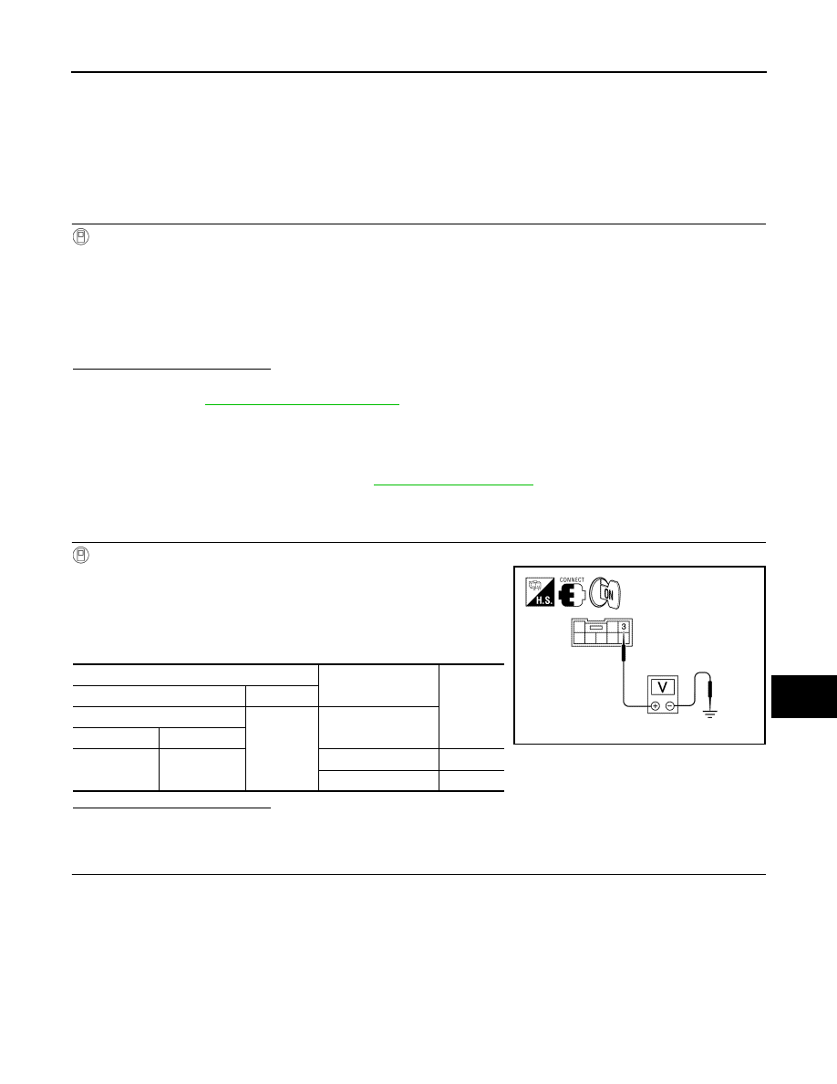
3. While operating the test item, check voltage between push-but-
ton ignition switch connector M38 terminal 3 and ground.
Is the inspection result normal?
YES
>> GO TO 4
NO
>> GO TO 2
2.
CHECK PUSH-BUTTON IGNITION SWITCH ILLUMINATION POWER SUPPLY OPEN CIRCUIT
ON
: Push-button ignition switch illumination ON
OFF
: Push-button ignition switch illumination OFF
Terminals
Test item
Voltage
(+)
(-)
Push-button ignition switch
Ground
ENGINE SW ILLUMI
Connector
Terminal
M38
3
ON
5.5V
OFF
0V
AWLIA1474ZZ