Nissan Maxima. Instruction - part 445
EC-264
< DTC/CIRCUIT DIAGNOSIS >
[VQ35DE]
P0171, P0174 FUEL INJECTION SYSTEM FUNCTION
For specification, refer to
EC-596, "Mass Air Flow Sensor"
Is the measurement value within the specification?
YES
>> GO TO 7.
NO
>> Check connectors for rusted terminals or loose connections in the mass air flow sensor circuit or
ground. Refer to
7.
CHECK FUNCTION OF FUEL INJECTOR
With CONSULT
1. Start engine.
2. Perform “POWER BALANCE” in “ACTIVE TEST” mode with CONSULT.
3. Check that each circuit produces a momentary engine speed drop.
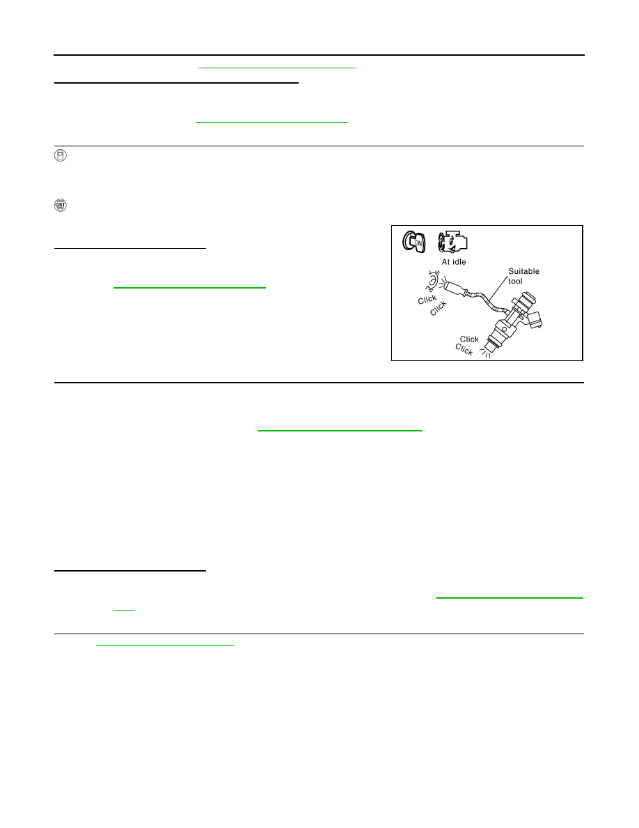
With GST
1. Let engine idle.
2. Listen to each fuel injector operating sound.
Is the inspection result normal?
YES
>> GO TO 8.
NO
>> Perform trouble diagnosis for FUEL INJECTOR, refer to
.
8.
CHECK FUEL INJECTOR
1. Turn ignition switch OFF.
2. Confirm that the engine is cooled down and there are no fire hazards near the vehicle.
3. Disconnect all fuel injector harness connectors.
4. Remove fuel tube assembly. Refer to
EM-43, "Removal and Installation"
.
Keep fuel hose and all fuel injectors connected to fuel tube.
5. For DTC P0171, reconnect fuel injector harness connectors on bank 1.
For DTC P0174, reconnect fuel injector harness connectors on bank 2.
6. Disconnect all ignition coil harness connectors.
7. Prepare pans or saucers under each fuel injector.
8. Crank engine for about 3 seconds.
For DTC P0171, check that fuel sprays out from fuel injectors on bank 1.
For DTC P0174, check that fuel sprays out from fuel injectors on bank 2.
Is the inspection result normal?
YES
>> GO TO 9.
NO
>> Replace fuel injectors from which fuel does not spray out. Refer to
. Always replace O-ring with new ones.
9.
CHECK INTERMITTENT INCIDENT
GI-41, "Intermittent Incident"
>> INSPECTION END
PBIB3332E
Fuel should be sprayed evenly for each fuel injector.