Nissan Maxima. Instruction - part 433


  Index      Nissan     Nissan Maxima (2009-2014 year) - Service and Repair Instruction


Search            copyright infringement  


Content   ..  431  432  433  434   ..


Nissan Maxima. Instruction - part 433


EC-216

< DTC/CIRCUIT DIAGNOSIS >

[VQ35DE]

P0128 THERMOSTAT FUNCTION

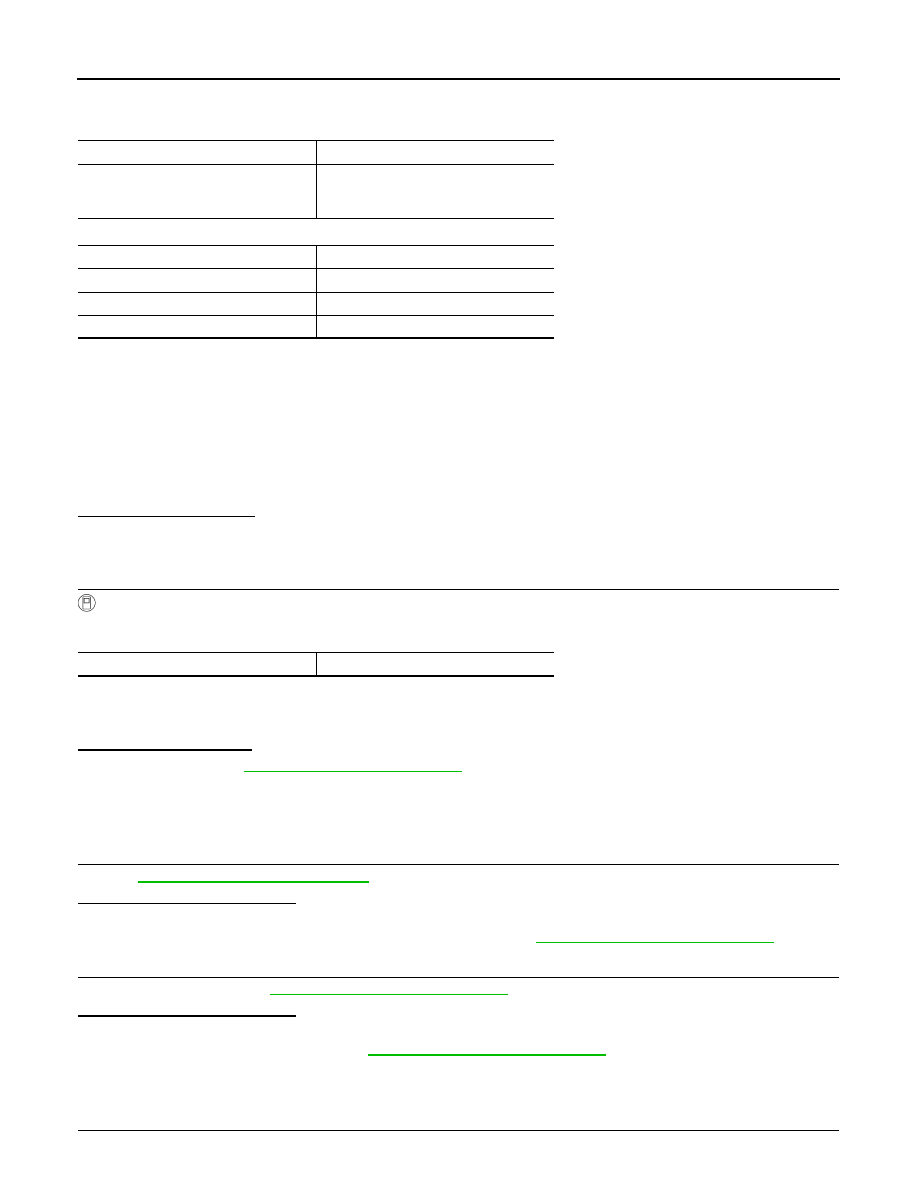
Drive the vehicle under the conditions instructed below until the difference between “COOLAN TEMP/S” and

“FUEL T/TMP SE” becomes at least 25

°C (45°F).

*: Example

-

STEP 2

Drive the vehicle at 50 km/h (32 MPH) or more with the difference between “COOLAN TEMP/S” and “FUEL

T/TMP SE” maintained at 25

°C (45°F) or more.

NOTE:

Keep the accelerator pedal as steady as possible during cruising.

-

STEP 3

Drive the vehicle at 50 km/h (32 MPH) or more until “COOLAN TEMP/S” increases by 7

°C (13°F).

NOTE:

Keep the accelerator pedal as steady as possible during cruising.

Is the condition satisfied?

YES

>> GO TO 4.

NO

>> GO TO 1.

4.

PERFORM DTC CONFIRMATION PROCEDURE-II

With CONSULT

1. Drive the vehicle until the following condition is satisfied.

CAUTION:

Always drive vehicle at safe speed.

2. Check 1st trip DTC.
Is 1st trip DTC detected?

YES

>> Proceed to 

EC-216, "Diagnosis Procedure"

.

NO

>> INSPECTION END

Diagnosis Procedure

INFOID:0000000010094927

1.

CHECK ENGINE COOLANT TEMPERATURE SENSOR

Refer to 

EC-216, "Component Inspection"

.

Is the inspection result normal?

YES

>> GO TO 2.

NO

>> Replace engine coolant temperature sensor. Refer to 

CO-24, "Removal and Installation"

.

2.

CHECK THERMOSTAT

Check thermostat. Refer to 

CO-22, "Removal and Installation"

.

Is the inspection result normal?

YES

>> INSPECTION END

NO

>> Replace thermostat. Refer to 

CO-22, "Removal and Installation"

.

Component Inspection

INFOID:0000000010094928

1.

CHECK ENGINE COOLANT TEMPERATURE SENSOR

COOLAN TEMP/S

71

°C (159°F) or less

FUEL T/TMP SE

Less than the value calculated by sub-
tracting 25

°C (45°F) from “COOLAN 

TEMP/S”.*

COOLAN TEMP/S

FUEL T/TMP SE

70

°C (158°F)

45

°C (113°F) or less

65

°C (149°F)

40

°C (104°F) or less

60

°C (140°F)

35

°C (95°F) or less

COOLAN TEMP/S

71

°C (159°F) or more

P0128 THERMOSTAT FUNCTION

EC-217

< DTC/CIRCUIT DIAGNOSIS >

[VQ35DE]

C

D

E

F

G

H

I

J

K

L

M

A

EC

N

P

O

1. Turn ignition switch OFF.

2. Disconnect engine coolant temperature sensor harness connector.

3. Remove engine coolant temperature sensor. Refer to 

CO-24, "Removal and Installation"

.

4. Check resistance between engine coolant temperature sensor

terminals as per the following.

Is the inspection result normal?

YES

>> INSPECTION END

NO

>> Replace engine coolant temperature sensor. Refer to

CO-24, "Removal and Installation"

.

Terminals

Condition

Resistance (k

Ω)

1 and 2

Temperature [

°C (°F)]

20 (68)

2.1 - 2.9

50 (122)

0.68 - 1.00

90 (194)

0.236 - 0.260

PBIB2005E

EC-218

< DTC/CIRCUIT DIAGNOSIS >

[VQ35DE]

P0130, P0150 A/F SENSOR 1

P0130, P0150 A/F SENSOR 1

Description

INFOID:0000000010094929

The air fuel ratio (A/F) sensor 1 is a planar one-cell limit current sen-

sor. The sensor element of the A/F sensor 1 is composed an elec-

trode layer, which transports ions. It has a heater in the element.
The sensor is capable of precise measurement   = 1, but also in the

lean and rich range. Together with its control electronics, the sensor
outputs a clear, continuous signal throughout a wide   range.

The exhaust gas components diffuse via the diffusion layer at the

sensor cell. An electrode layer is applied voltage, and this current

relative oxygen density in lean. Also this current relative hydrocar-

bon density in rich.

Therefore, the A/F sensor 1 is able to indicate air fuel ratio by this

electrode layer of current. In addition, a heater is integrated in the

sensor to ensure the required operating temperature of about 800

°C

(1,472

°F).

DTC Logic

INFOID:0000000010094930

DTC DETECTION LOGIC

To judge malfunctions, the diagnosis checks that the A/F signal computed by ECM from the A/F sensor 1 sig-

nal fluctuates according to fuel feedback control.

DTC CONFIRMATION PROCEDURE

1.

PRECONDITIONING

If DTC Confirmation Procedure has been previously conducted, always perform the following before conduct-

ing the next test.

1. Turn ignition switch OFF and wait at least 10 seconds.

2. Turn ignition switch ON.

3. Turn ignition switch OFF and wait at least 10 seconds.

TESTING CONDITION:

Before performing the following procedure, confirm that battery voltage is more than 11 V at idle.

>> GO TO 2.

JMBIA0112GB

PBIB3354E

DTC No.

Trouble diagnosis name

DTC detecting condition

Possible Cause

P0130

Air fuel ratio (A/F) sensor 1 
(bank 1) circuit

A)

The A/F signal computed by ECM from the A/F 
sensor 1 signal is constantly in a range other 
than approx. 2.2 V.

• Harness or connectors

(The sensor circuit is open or 
shorted.)

• A/F sensor 1

B)

The A/F signal computed by ECM from the A/F 
sensor 1 signal is constantly approx. 2.2 V.

P0150

Air fuel ratio (A/F) sensor 1 
(bank 2) circuit

A)

The A/F signal computed by ECM from the A/F 
sensor 1 signal is constantly in a range other 
than approx. 2.2 V.

B)

The A/F signal computed by ECM from the A/F 
sensor 1 signal is constantly approx. 2.2 V.

P0130, P0150 A/F SENSOR 1

EC-219

< DTC/CIRCUIT DIAGNOSIS >

[VQ35DE]

C

D

E

F

G

H

I

J

K

L

M

A

EC

N

P

O

2.

PERFORM DTC CONFIRMATION PROCEDURE FOR MALFUNCTION A

1. Start engine and warm it up to normal operating temperature.

2. Let it idle for 2 minutes.

3. Check 1st trip DTC.
Is 1st trip DTC detected?

YES

>> Go to 

EC-220, "Diagnosis Procedure"

.

NO-1 >> With CONSULT: GO TO 3.

NO-2 >> Without CONSULT: GO TO 7.

3.

CHECK AIR FUEL RATIO (A/F) SENSOR 1 FUNCTION

1. Start engine and warm it up to normal operating temperature.

2. Select “A/F SEN1 (B1)” or “A/F SEN1 (B2)” in “DATA MONITOR” mode with CONSULT.

3. Check “A/F SEN1 (B1)” or “A/F SEN1 (B2)” indication.
Does the indication fluctuate around 2.2 V?

YES

>> GO TO 4.

NO

>> Go to 

EC-220, "Diagnosis Procedure"

.

4.

PERFORM DTC CONFIRMATION PROCEDURE FOR MALFUNCTION B-I

1. Select “A/F SEN1 (B1) P1276” (for DTC P0130) or “A/F SEN1 (B2) P1286” (for DTC P0150) of “A/F

SEN1” in “DTC WORK SUPPORT” mode with CONSULT.

2. Touch “START”.

3. When the following conditions are met, “TESTING” will be displayed on the CONSULT screen.

If “TESTING” is not displayed after 20 seconds, retry from step 2.

CAUTION:

Always drive vehicle at a safe speed.

Is “TESTING” displayed on CONSULT screen?

YES

>> GO TO 5.

NO

>> Check A/F sensor 1 function again. GO TO 3.

5.

PERFORM DTC CONFIRMATION PROCEDURE FOR MALFUNCTION B-II

Release accelerator pedal fully.

NOTE:

Never apply brake when releasing the accelerator pedal.
Which does “TESTING” change to?

COMPLETED>>GO TO 6.

OUT OF CONDITION>>Retry DTC CONFIRMATION PROCEDURE. GO TO 4.

6.

PERFORM DTC CONFIRMATION PROCEDURE FOR MALFUNCTION B-III

Touch “SELF-DIAG RESULT”.
Which is displayed on CONSULT screen?

OK

>> INSPECTION END

NG

>> Go to 

EC-220, "Diagnosis Procedure"

.

7.

PERFORM COMPONENT FUNCTION CHECK FOR MALFUNCTION B

Perform component function check. Refer to 

EC-220, "Component Function Check"

.

NOTE:

Use component function check to check the overall function of the A/F sensor 1 circuit. During this check, a

1st trip DTC might not be confirmed.
Is the inspection result normal?

YES

>> INSPECTION END

ENG SPEED

1,000 - 3,200 rpm

VHCL SPEED SE

More than 64 km/h (40 mph)

B/FUEL SCHDL

1.0 - 8.0 msec

Selector lever

D position


Content   ..  431  432  433  434   ..