Nissan Altima HL32 Hybrid. Instruction - part 978
SE-14
< SYMPTOM DIAGNOSIS >
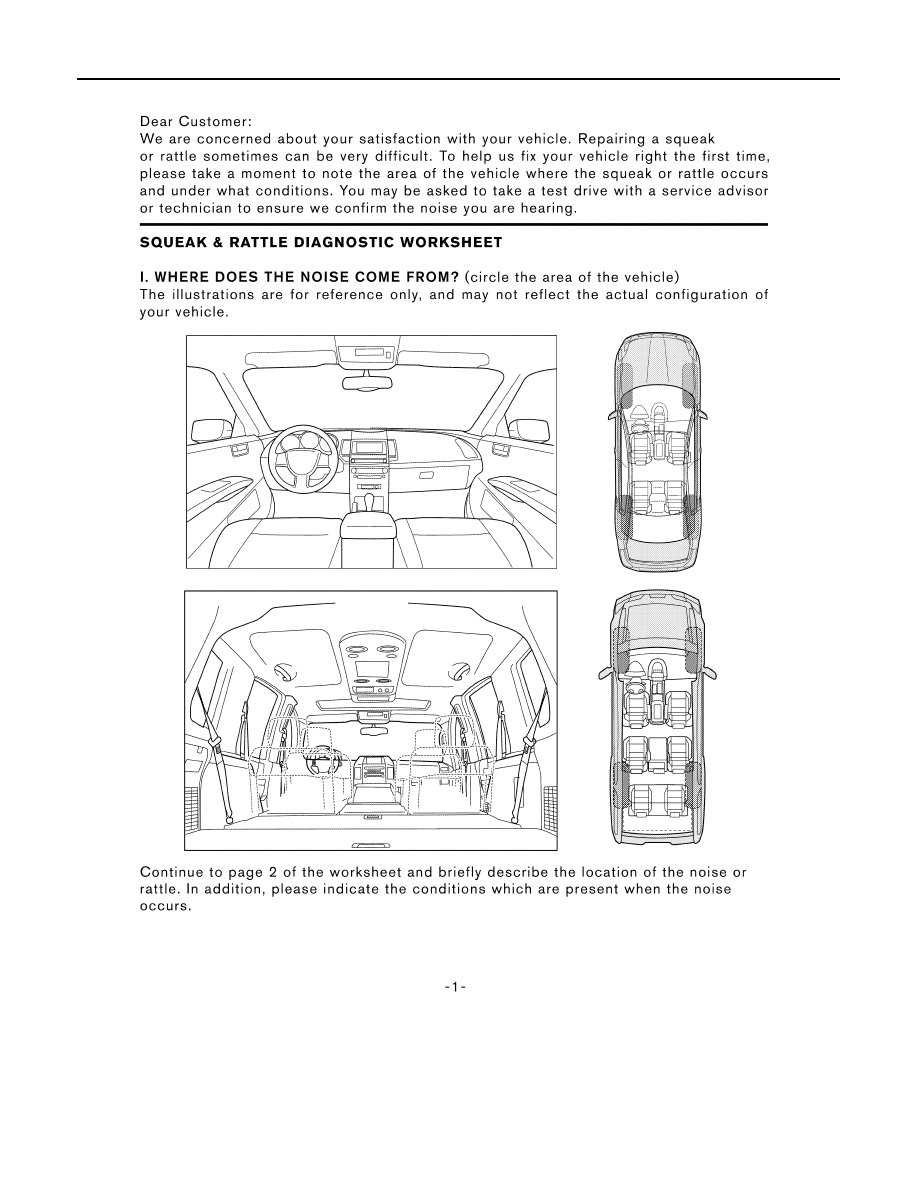
SQUEAK AND RATTLE TROUBLE DIAGNOSES
Diagnostic Worksheet
INFOID:0000000004215450
LAIA0072E
|
|
|
SE-14 < SYMPTOM DIAGNOSIS > SQUEAK AND RATTLE TROUBLE DIAGNOSES Diagnostic Worksheet INFOID:0000000004215450 LAIA0072E |