Nissan Altima HL32 Hybrid. Instruction - part 764


  Index      Nissan     Nissan Altima HL32 Hybrid (2009 year) - Service and Repair Instruction


Search            copyright infringement  


Content   ..  762  763  764  765   ..


Nissan Altima HL32 Hybrid. Instruction - part 764


LAN-10

< FUNCTION DIAGNOSIS >

[CAN FUNDAMENTAL]

TROUBLE DIAGNOSIS

TROUBLE DIAGNOSIS

Condition of Error Detection

INFOID:0000000004219016

“U1000” or “U1001” is indicated on SELF-DIAG RESULTS on CONSULT-III if CAN communication signal is

not transmitted or received between units for 2 seconds or more.

CAN COMMUNICATION SYSTEM ERROR

• CAN communication line open (CAN-H, CAN-L, or both)

• CAN communication line short (ground, between CAN communication lines, other harnesses)

• Error of CAN communication control circuit of the unit connected to CAN communication line

WHEN “U1000” OR “U1001” IS INDICATED EVEN THOUGH CAN COMMUNICATION SYSTEM IS
NORMAL

• Removal/installation of parts: Error may be detected when removing and installing CAN communication unit

and related parts while turning the ignition switch ON. (A DTC except for CAN communication may be

detected.)

• Fuse blown out (removed): CAN communication of the unit may cease.

• Voltage drop: Error may be detected if voltage drops due to discharged battery when turning the ignition

switch ON (Depending on the control unit which carries out CAN communication).

• Error may be detected if the power supply circuit of the control unit, which carries out CAN communication,

malfunctions (Depending on the control unit which carries out CAN communication).

• Error may be detected if reprogramming is not completed normally.

NOTE:

CAN communication system is normal if “U1000” or “U1001” is indicated on SELF-DIAG RESULTS of CON-

SULT-III under the above conditions. Erase the memory of the self-diagnosis of each unit.

Symptom When Error Occurs in CAN Communication System

INFOID:0000000004219017

In CAN communication system, multiple units mutually transmit and receive signals. Each unit cannot transmit

and receive signals if any error occurs on CAN communication line. Under this condition, multiple control units

related to the root cause malfunction or go into fail-safe mode.

ERROR EXAMPLE

NOTE:

• Each vehicle differs in symptom of each unit under fail-safe mode and CAN communication line wiring.

• Refer to 

LAN-23, "Abbreviation List"

 for the unit abbreviation.

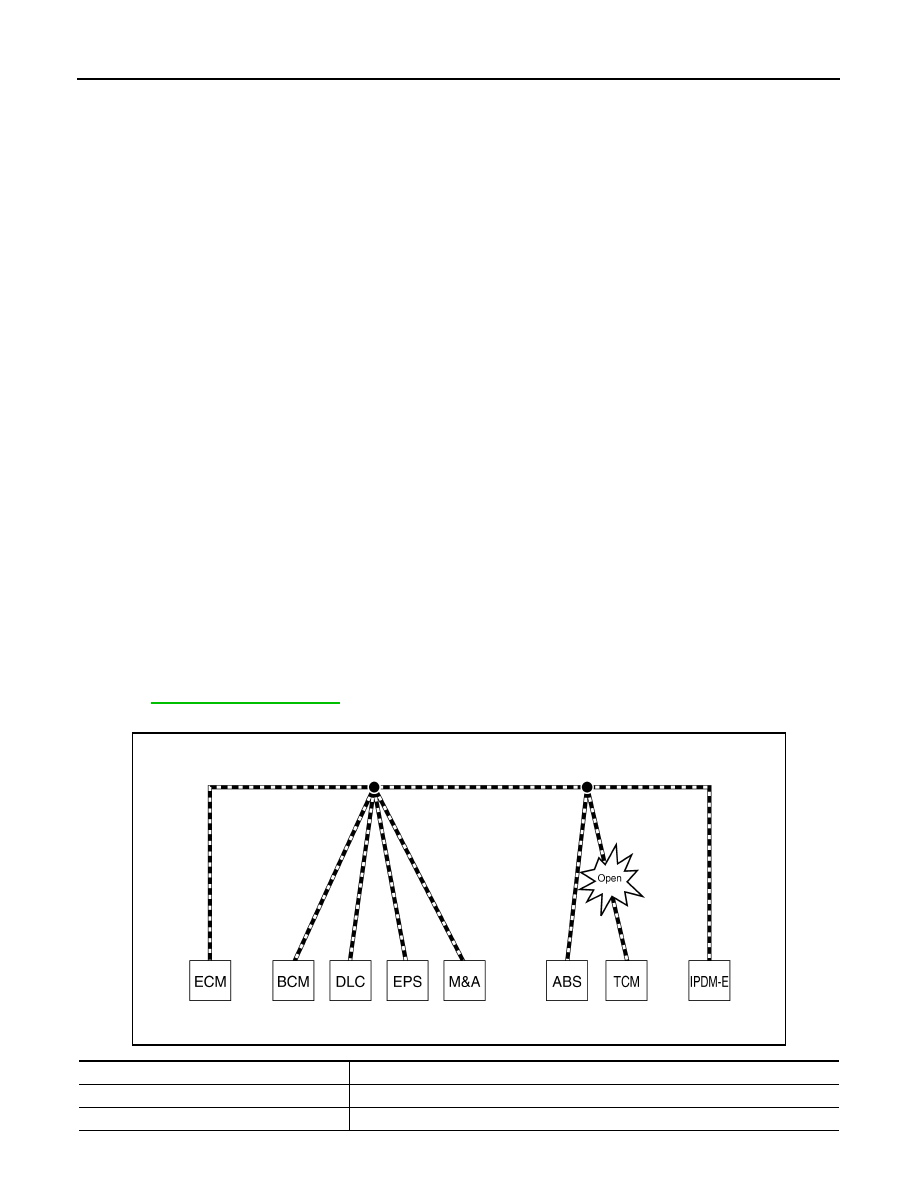
Example: TCM branch line open circuit

SKIB8738E

Unit name

Symptom

ECM

Engine torque limiting is affected, and shift harshness increases.

BCM

Reverse warning chime does not sound.

LAN

TROUBLE DIAGNOSIS

LAN-11

< FUNCTION DIAGNOSIS >

[CAN FUNDAMENTAL]

C

D

E

F

G

H

I

J

K

L

B

A

O

P

N

Example: Data link connector branch line open circuit

NOTE:

• When data link connector branch line is open, transmission and reception of CAN communication signals

are not affected. Therefore, no symptoms occur. However, be sure to repair malfunctioning circuit.

• The model (all units on CAN communication system are Diag on CAN) cannot perform CAN diagnosis with

CONSULT-III if the following error occurs. The error is judged by the symptom.

EPS control unit

Normal operation.

Combination meter

• Shift position indicator and OD OFF indicator turn OFF.
• Warning lamps turn ON.

ABS actuator and electric unit (control unit)

Normal operation.

TCM

No impact on operation.

IPDM E/R

Normal operation.

Unit name

Symptom

SKIB8739E

Unit name

Symptom

ECM

Normal operation.

BCM

EPS control unit

Combination meter

ABS actuator and electric unit (control unit)

TCM

IPDM E/R

Error

Difference of symptom

Data link connector branch line open circuit

Normal operation.

CAN-H, CAN-L harness short-circuit

Most of the units which are connected to the CAN communication 
system enter fail-safe mode or are deactivated.

LAN-12

< FUNCTION DIAGNOSIS >

[CAN FUNDAMENTAL]

TROUBLE DIAGNOSIS

Example: Main Line Between Data Link Connector and ABS Actuator and Electric Unit (Control Unit) Open Circuit

Example: CAN-H, CAN-L Harness Short Circuit

SKIB8740E

Unit name

Symptom

ECM

Engine torque limiting is affected, and shift harshness increases.

BCM

• Reverse warning chime does not sound.
• The front wiper moves under continuous operation mode even though the front wip-

er switch being in the intermittent position.

EPS control unit

The steering effort increases.

Combination meter

• The shift position indicator and OD OFF indicator turn OFF.
• The speedometer is inoperative.
• The odo/trip meter stops.

ABS actuator and electric unit (control unit)

Normal operation.

TCM

No impact on operation.

IPDM E/R

When the ignition switch is ON,
• The headlamps (Lo) turn ON.
• The cooling fan continues to rotate.

SKIB8741E

LAN

TROUBLE DIAGNOSIS

LAN-13

< FUNCTION DIAGNOSIS >

[CAN FUNDAMENTAL]

C

D

E

F

G

H

I

J

K

L

B

A

O

P

N

CAN Diagnosis with CONSULT-III

INFOID:0000000004219018

CAN diagnosis on CONSULT-III extracts the root cause by receiving the following information.

• Response to the system call

• Control unit diagnosis information

• Self-diagnosis

• CAN diagnostic support monitor

Self-Diagnosis

INFOID:0000000004219019

*: Hybrid vehicle control ECU may display one or more DTCs listed as follows; U1001 (146), U1001 (435), U1001 (594), U1001 (827),
U1001 (919), U1001 (920).

Unit name

Symptom

ECM

• Engine torque limiting is affected, and shift harshness increases.
• Engine speed drops.

BCM

• Reverse warning chime does not sound.
• The front wiper moves under continuous operation mode even though the front 

wiper switch being in the intermittent position.

• The room lamp does not turn ON.
• The engine does not start (if an error or malfunction occurs while turning the igni-

tion switch OFF.)

• The steering lock does not release (if an error or malfunction occurs while turning 

the ignition switch OFF.)

EPS control unit

The steering effort increases.

Combination meter

• The tachometer and the speedometer do not move.
• Warning lamps turn ON.
• Indicator lamps do not turn ON.

ABS actuator and electric unit (control unit)

Normal operation.

TCM

No impact on operation.

IPDM E/R

When the ignition switch is ON,
• The headlamps (Lo) turn ON.
• The cooling fan continues to rotate.

DTC

Self-diagnosis item

 (CONSULT-III indication)

DTC detection condition

Inspection/Action

U0164

LOST COMM (HVAC)

When ECM is not transmitting or receiving CAN 
communication signal of OBD (emission-related 
diagnosis) from A/C auto amp. for 2 seconds or 
more.

Start the inspection. Re-
fer to the applicable sec-
tion of the indicated 
control unit.

U1000

CAN COMM CIRCUIT

When a control unit (except for ECM) is not 
transmitting or receiving CAN communication 
signal for 2 seconds or more.

U1001*

CAN COMM CIRCUIT

When ECM is not transmitting or receiving CAN 
communication signal other than OBD (emis-
sion-related diagnosis) for 2 seconds or more.

When hybrid vehicle control ECU is not transmit-
ting or receiving CAN communication signal for 
2 seconds or more.

U1002

SYSTEM COMM

When a control unit is not transmitting or receiv-
ing CAN communication signal for 2 seconds or 
less.

U1010

CONTROL UNIT(CAN)

When an error is detected during the initial diag-
nosis for CAN controller of each control unit.

Replace the control unit 
indicating “U1010” or 
“P0607”.

P0607

ECM


Content   ..  762  763  764  765   ..