Nissan Altima HL32 Hybrid. Instruction - part 693


  Index      Nissan     Nissan Altima HL32 Hybrid (2009 year) - Service and Repair Instruction


Search            copyright infringement  


Content   ..  691  692  693  694   ..


Nissan Altima HL32 Hybrid. Instruction - part 693


P3004-131

HBC-521

< COMPONENT DIAGNOSIS >

D

E

F

G

H

I

J

K

L

M

A

B

HBC

N

O

P

4. Measure the resistance according to the value(s) in the table below.

OK or NG

OK

>> GO TO 10.

NG

>> Repair or replace harness or connector.

10.

CHECK CONDITION OF MAIN BATTERY CABLE CONNECTION(S)

CAUTION:

Be sure to wear insulated gloves.

1. Check that the service plug grip is not installed.

2. Check the connections between the main battery cable and the

HV relay assembly.

NOTE:

The main battery cable and HV battery are supplied as one unit.

A, B, C or D

A

>> GO TO 11.

B

>> Connect securely.

C

>> Replace HV relay assembly. (See 

HBB-105, "Removal and Installation"

).

D

>> Replace HV battery assembly. (See 

HBB-97, "Removal and Installation"

).

11.

CHECK HV BATTERY ASSEMBLY

CAUTION:

Be sure to wear insulated gloves.

1. Check that the service plug grip is not installed.

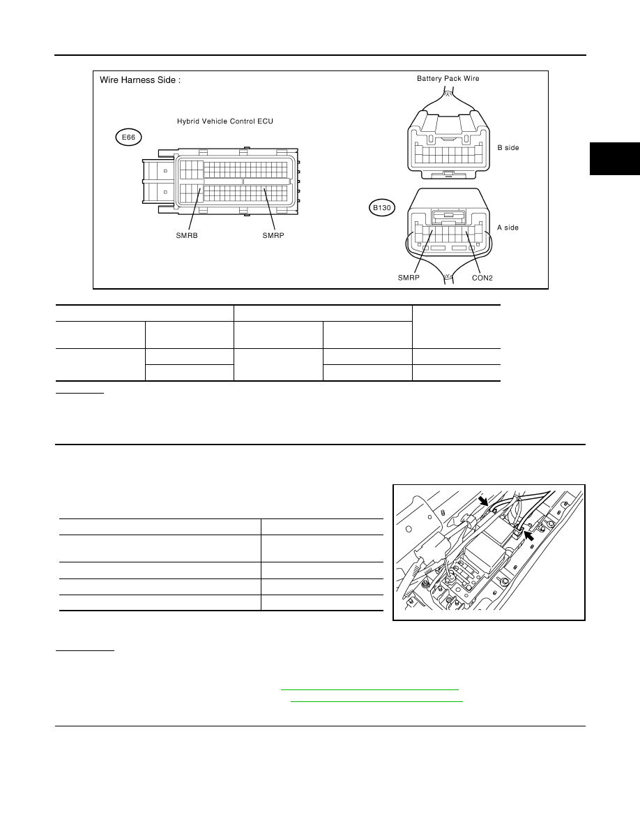
Hybrid Vehicle Control ECU

Battery Pack Wire

Resistance

Harness

connector

Terminal

Harness

connector

Terminal

E66

169 (SMRB)

B130

3 (CON2)

Below 1

77 (SMRP)

8 (SMRP)

Below 1

JMCIA0204GB

DTC No.

Related Part

 The connectors are connected securely and there 
are no contact problems.

A

The connectors are not connected securely.

B

The HV relay assembly connector is damaged.

C

The main battery cable is damaged.

D

JMCIA0205GB

HBC-522

< COMPONENT DIAGNOSIS >

P3004-131

2. Disconnect the main battery cable from the HV relay assembly

(See 

HBB-105, "Removal and Installation"

).

3. Measure the voltage according to the value(s) in the table below.

CAUTION:

Do not allow the probes of the electrical tester to contact

each other during this inspection.

OK or NG

OK

>> GO TO 12.

NG

>> Replace HV battery assembly. (See 

HBB-97, "Removal

and Installation"

).

12.

CHECK CONNECTOR CONNECTION CONDITION (HV RELAY ASSEMBLY CONNECTOR)

CAUTION:

Be sure to wear insulated gloves.

1. Turn ignition switch OFF and remove the service plug grip (See 

HBC-632, "Precautions for Inspecting the

Hybrid Control System"

).

NOTE:

After removing the service plug grip, do not turn ignition switch ON (READY), unless instructed by the ser-

vice instruction because this may cause a malfunction.

2. Check the connections of the HV relay assembly connectors.

NOTE:

For the removal procedure of the HV relay assembly connector, (See 

HBB-105, "Removal and Installa-

tion"

).

OK or NG

OK

>> GO TO 13.

NG

>> Connect securely.

13.

CHECK HARNESS AND CONNECTOR (HV RELAY ASSEMBLY - BATTERY PACK WIRE CONNEC-

TOR)

CAUTION:

Be sure to wear insulated gloves.

1. Check that the service plug grip is not installed.

2. Disconnect the n3 HV relay assembly connector.

Harness connector

Service plug grip

Voltage

Harness

connector

Terminal

Component 

connector

Terminal

s1

1

1

114 to 190V

t1

1

2

90 to 190V

JMCIA0164GB

Result:

The connectors are connected securely and 
there are no contact problems.

JMCIA0206GB

P3004-131

HBC-523

< COMPONENT DIAGNOSIS >

D

E

F

G

H

I

J

K

L

M

A

B

HBC

N

O

P

3. Measure the resistance according to the value(s) in the table

below.

OK or NG

OK

>> GO TO 14.

NG

>> Repair or replace harness or connector.

14.

CHECK CONNECTOR CONNECTION CONDITION (HYBRID VEHICLE CONVERTER CONNECTOR)

See 

HBC-140, "Diagnosis Procedure"

.

OK or NG

OK

>> GO TO 15.

NG

>> Connect securely.

15.

CHECK HARNESS AND CONNECTOR (HYBRID VEHICLE CONVERTER - BATTERY PACK WIRE

CONNECTOR)

CAUTION:

Be sure to wear insulated gloves.

1. Check that the service plug grip is not installed.

2. Disconnect the n4 hybrid vehicle converter (DC/DC converter) connector (See 

HBB-103, "Removal and

Installation"

).

3. Measure the resistance according to the value(s) in the table below.

Battery pack wire connector

HV relay assembly

Resistance

Component

connector

Terminal

Harness

connector

Terminal

B130

3 (CON2)

n3

3 (CON2)

Below 1

JMCIA0207GB

JMCIA0208GB

HBC-524

< COMPONENT DIAGNOSIS >

P3004-131

OK or NG

OK

>> GO TO 16.

NG

>> Repair or replace harness or connector.

16.

INSPECT HV RELAY ASSEMBLY (SMRB)

CAUTION:

Be sure to wear insulated gloves and protective goggles.

1. Check that the service plug grip is not installed.

2. Remove the HV relay assembly from the vehicle (See 

HBB-105, "Removal and Installation"

).

3. Measure the resistance according to the value(s) in the table

below.

4. Measure the resistance according to the value(s) in the table

below.

OK or NG

OK

>> GO TO 17.

NG

>> Replace hv relay assembly. (See 

HBB-105, "Removal and Installation"

)

17.

CHECK FOR INTERMITTENT PROBLEM

NOTE:

If DTC P3004-131 is output again after performing the inspection, replace the hybrid vehicle converter (DC/DC

converter). If DTC P3004-131 is not output, replace the HV relay assembly.
YES or NO

YES

>> Replace hybrid vehicle converter. (See 

HBB-103, "Removal and Installation"

).

NO

>> Replace hv relay assembly. (See 

HBB-105, "Removal and Installation"

).

Battery pack wire

Hybrid vehicle converter

(DC/DC converter)

Resistance

Component

connector

Terminal

Harness

connector

Terminal

B130

8 (SMRP)

n4

4 (SMRP)

Below 1

HV relay assembly

HV relay assembly

Resistance

Component

connector

Terminal

Component

connector

Terminal

E308

21

s1

1

Below 1

When battery voltage (12 

V) applied to terminals n3- 

2 and n3-3)

HV relay assembly

HV relay assembly

Resistance

Component

connector

Terminal

Component

connector

Terminal

n3

3 (CON2)

n3

2 (GND)

18.8 to 32.1 

Ω at -35 to 

80

°C (-31 to 176°F)

JMCIA0209GB


Content   ..  691  692  693  694   ..