Nissan Altima HL32 Hybrid. Instruction - part 633
P0A78-505, P0A78-506
HBC-281
< COMPONENT DIAGNOSIS >
D
E
F
G
H
I
J
K
L
M
A
B
HBC
N
O
P
Diagnosis Procedure
INFOID:0000000004211941
1.
PRECONDITIONING
• Before inspecting the high-voltage system or disconnecting the low voltage connector of the inverter with
converter assembly, take safety precautions such as wearing insulated gloves and removing the service
plug grip to prevent electrical shocks. After removing the service plug grip, put it in your pocket to prevent
other technicians from accidentally reconnecting it while you are working on the high-voltage system.
• After disconnecting the service plug grip, wait for at least 10 minutes before touching any of the high-voltage
connectors or terminals.
• Waiting for at least 10 minutes is required to discharge the high-voltage capacitor inside the inverter with
converter assembly.
>> GO TO 2.
2.
CHECK DTC OUTPUT (HYBRID SYSTEM)
1. Turn ignition switch ON.
2. Check DTC.
NOTE:
P0A78-505 or 506 may be set due to a malfunction which also causes DTCs in the table above to be set.
In this case, first troubleshoot the output DTCs in the table above. Then, perform a test to attempt to
reproduce the problems, and check that no DTCs are output.
Is DTC detected?
YES
>> Go to Diagnosis Procedure relevant to output DTC.
NO
>> GO TO 3.
3.
CHECK CONNECTOR CONNECTION CONDITION (INVERTER WITH CONVERTER ASSEMBLY CON-
NECTOR)
DTC No.
INF code
Trouble diagnosis name
DTC detecting condition
Possible cause
P0A78
505
Drive Motor “A” Inverter
Performance
Motor inverter fail signal detection
(overcurrent due to MG ECU mal-
function)
• Wire harness or connector
• Hybrid transaxle
• Inverter with converter assembly
506
Motor inverter fail signal detection
(overcurrent due to hybrid transax-
le malfunction)
• Wire harness or connector
• Hybrid transaxle
• Inverter with converter assembly
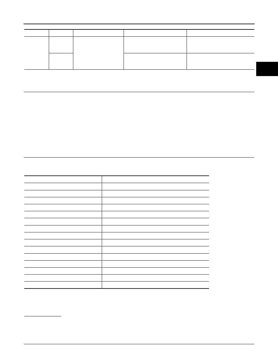
DTC No.
Relevant Diagnosis
P0A1D (Except INF code 390)
Hybrid Powertrain Control Module
P0A1A (all INF codes)
Generator Control Module
P0A1B (all INF codes)
Drive Motor “A” Control Module
P0A72 (all INF codes)
Generator Phase V Current
P0A75 (all INF codes)
Generator Phase W Current
P0A60 (all INF codes)
Drive Motor “A” Phase V Current
P0A63 (all INF codes)
Drive Motor “A” Phase W Current
P0A4B-253
Generator Position Sensor Circuit
P0A4D-255
Generator Position Sensor Circuit Low
P0A4C-513
Generator Position Sensor Circuit Range / Performance
P0A3F-243
Drive Motor “A” Position Sensor Circuit
P0A41-245
Drive Motor “A” Position Sensor Circuit Low
P0A40-500
Drive Motor “A” Position Sensor Circuit Range / Performance
P0A78-266, 267, 523, 586
Drive Motor “A” Inverter Performance
P0A94-585, 587, 589, 590
DC/DC Converter Performance