Nissan Altima HL32 Hybrid. Instruction - part 488
HA-14
< PREPARATION >
PREPARATION
Commercial Service Tool
INFOID:0000000004215271
CAUTION:
* Avoid using tools that have been used for vehicles with conventional A/C oil as much as possible. This will result in insula-
tion performance deterioration. A tool that has been used three times or less can be reused if ann appropriate one is not avail-
able.
Tool number
Tool name
Description
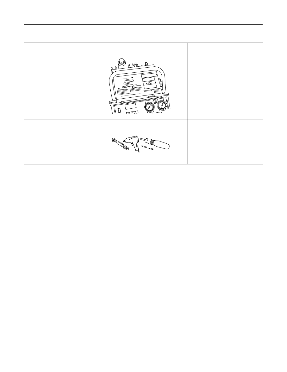
J-41810-NI
Refrigerant identifier equipment
HFC 134a (R-134a)*
Checking refrigerant purity and system
contamination
Power tool
Removing bolts, screws and nuts
RJIA0197E
PIIB1407E