Nissan Altima HL32 Hybrid. Instruction - part 452


  Index      Nissan     Nissan Altima HL32 Hybrid (2009 year) - Service and Repair Instruction


Search            copyright infringement  


Content   ..  450  451  452  453   ..


Nissan Altima HL32 Hybrid. Instruction - part 452


FRONT DRIVE SHAFT

FAX-13

< ON-VEHICLE REPAIR >

C

E

F

G

H

I

J

K

L

M

A

B

FAX

N

O

P

REMOVAL

1. Remove wheel and tire. Refer to 

WT-62, "Adjustment"

.

2. Remove wheel sensor from steering knuckle. Refer to 

BRC-202, "Removal and Installation"

.

3. Remove cotter pin. Then remove lock nut from drive shaft using power tool.
4. Remove brake hose lock plate. Then remove brake hose from strut. 
5. Remove the lower ball joint pinch bolt using power tool, then separate lower ball joint from steering

knuckle. Refer to 

FSU-13, "Exploded View"

.

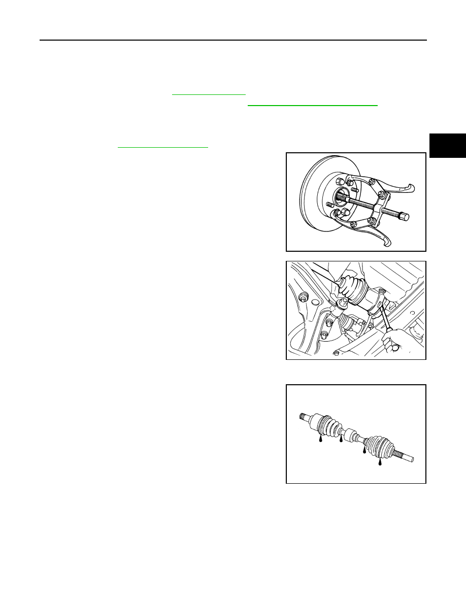
6. Remove drive shaft from wheel hub and bearing assembly,

using a puller or suitable tool.

CAUTION:

• When removing drive shaft, do not apply an excessive

angle to drive shaft joint. Also be careful not to exces-

sively extend slide joint.

7. Remove retaining bracket bolts using power tool, and pry drive

shaft from transaxle.

INSPECTION AFTER REMOVAL

• Move joint up/down, left/right, and in axial direction. Check for any rough movement or significant looseness.

• Check boot for cracks or other damage, and for grease leakage.

• If damaged, disassemble drive shaft to verify damage, and repair

or replace as necessary.

INSTALLATION

Installation is in the reverse order of removal.

CAUTION:

Do not reuse non-reusable parts.

1.

Cotter pin

2.

Drive shaft

3.

Retaining bracket

4.

Support bearing bracket

5.

Circlip

SDIA0972J

SFA989

WDIA0369E

FAX-14

< ON-VEHICLE REPAIR >

FRONT DRIVE SHAFT

• In order to prevent damage to differential side oil seal, place Tool

(A) onto oil seal before inserting drive shaft as shown. Slide drive

shaft into slide joint and tap with a hammer to install securely.

• Install new circlip on drive shaft in the circular clip groove on tran-

saxle side. Refer to 

FAX-15, "Disassembly and Assembly (Left

Side)"

.

CAUTION:

Make sure the new circlip on the drive shaft is securely fas-

tened.

• After its insertion, try to pull the flange out of the slide joint by hand.

If it pulls out, the circlip is not properly meshed with the transaxle side gear.

Tool number (A)

: KV38106800 (J-34297)

WDIA0298E

FRONT DRIVE SHAFT

FAX-15

< DISASSEMBLY AND ASSEMBLY >

C

E

F

G

H

I

J

K

L

M

A

B

FAX

N

O

P

DISASSEMBLY AND ASSEMBLY

FRONT DRIVE SHAFT

Disassembly and Assembly (Left Side)

INFOID:0000000004212412

DISASSEMBLY

Transaxle Side

1. Mount front drive shaft in a vise.

CAUTION:

When mounting shaft in a vise, always use copper or aluminum plates between vise and shaft.

2. Remove boot bands and slide the boot back.
3. Remove circlip and dust shield from slide joint housing.
4. Put matching marks on slide joint housing and shaft before separating joint assembly.
5. Remove stopper ring with a suitable tool, then pull out slide joint

housing.

1.

Circlip

2.

Dust shield

3.

Slide joint housing

4.

Snap ring

5.

Spider assembly

6.

Stopper ring

7.

Boot band

8.

Boot

9.

Shaft

10. Damper band

11. Damper

12. Boot band

13. Boot

14. Ball cage / Steel ball / Inner race assembly 15. Circlip

16. Joint sub-assembly

Front

WDIA0354E

SFA476

FAX-16

< DISASSEMBLY AND ASSEMBLY >

FRONT DRIVE SHAFT

6. Put matching marks on spider assembly and shaft.

7. Remove snap ring using a suitable tool, then remove spider

assembly from shaft.

8. Remove boot from shaft.
9. Clean the old grease off of the slide joint assembly.

Wheel Side

1. Mount the front drive shaft in a vise.

CAUTION:

When mounting shaft in a vise, always use copper or aluminum plates between vise and shaft.

2. Remove boot bands and slide the boot back.
3. Screw a sliding hammer or suitable tool 30 mm (1.18 in) or more

into threaded part of joint sub-assembly. Pull joint sub-assembly

out of shaft.

CAUTION:

• Align sliding hammer or suitable tool and drive shaft then

remove joint sub-assembly by pulling directly.

• If joint sub-assembly cannot be removed after five or

more unsuccessful attempts, replace the entire drive shaft

assembly.

4. Remove boot from shaft.
5. Remove circlip from shaft.
6. While rotating ball cage, clean the old grease off of the joint sub-assembly.

Damper

• Remove damper bands, then remove damper from shaft.

INSPECTION AFTER DISASSEMBLY

Shaft

• Replace shaft if there is bending, cracking, or other damage.

Joint Sub-Assembly

• Make sure there is no rough rotation or unusual axial looseness.

• Make sure there is no foreign material inside joint sub-assembly.

• Check joint sub-assembly for compression scars, cracks or fractures.

CAUTION:

If there are any irregular conditions of joint sub-assembly components, replace the entire joint sub-

assembly.

SFA963

SFA612

SDIA0606E


Content   ..  450  451  452  453   ..