Nissan Altima HL32 Hybrid. Instruction - part 388


  Index      Nissan     Nissan Altima HL32 Hybrid (2009 year) - Service and Repair Instruction


Search            copyright infringement  


Content   ..  386  387  388  389   ..


Nissan Altima HL32 Hybrid. Instruction - part 388


EM-66

< ON-VEHICLE REPAIR >

[QR25DE]

CYLINDER HEAD

7. Install valve collet using Tool.

• Compress valve spring with valve spring compressor. Install valve collet with magnet hand.

• Tap stem edge lightly with plastic hammer after installation to check its installed condition.

8. Install valve lifter.
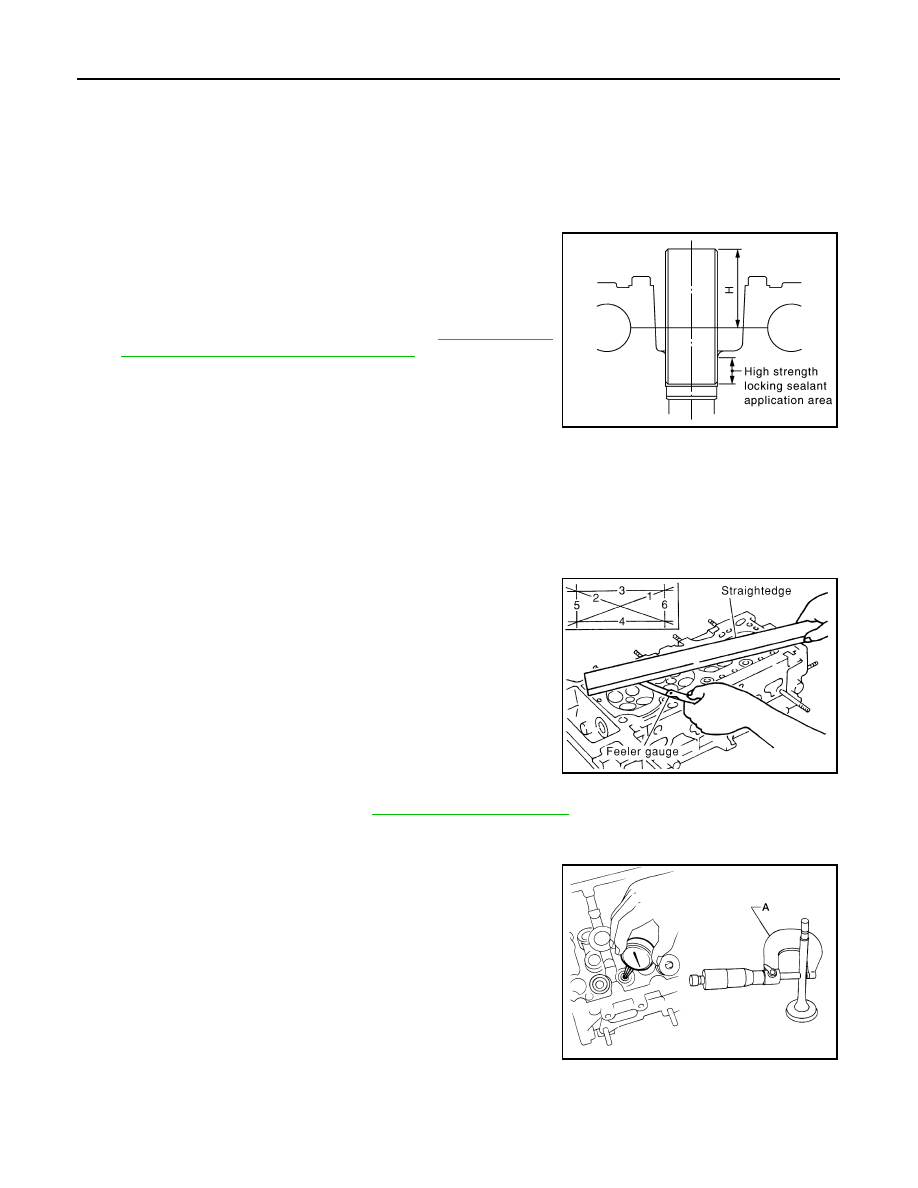
9. Install spark plug tube.
a. Remove old liquid gasket from cylinder head side mounting

hole.

b. Apply liquid gasket all around on spark plug tube with a 12 mm

(0.47 in) width from edge of spark plug tube on the press fit side.

• Use Three Bond or equivalent. Refer to 

GI-15, "Recom-

mended Chemical Products and Sealants"

.

c.

Press fit spark plug tube so that height is to (H) as shown.

CAUTION:

• When press fitting be careful not to deform spark plug tube.

• After press fitting, wipe off any protruding liquid gasket on top surface of cylinder head.

10. Install spark plug using suitable tool.

Inspection After Disassembly

INFOID:0000000004211258

CYLINDER HEAD DISTORTION

1. Wipe off oil and remove water scale deposits, old gasket, old

sealer, and carbon with a scraper.

CAUTION:

Use care not to allow gasket debris to enter passages for oil

or water.

2. At each of several locations on bottom surface of cylinder head,

measure distortion in six directions.

VALVE DIMENSIONS

Check dimensions of each valve. Refer to 

EM-98, "Standard and Limit"

.

VALVE GUIDE CLEARANCE

• Measure diameter of valve stem using suitable tool (A) as shown.

• Measure inner diameter of valve guide with a bore gauge as shown.

Tool number

: KV10116200 (J-26336-B)
: KV10115900 (J-26336-20)

Press fit height (H) standard value

: 41.7 mm (1.642 in)

PBIC2713E

Limit

: 0.1 mm (0.004 in) 

PBIC0075E

Standard
Intake

: 5.965 - 5.980 mm (0.2348 - 0.2354 in)

Exhaust

: 5.955 - 5.970 mm (0.2344 - 0.2350 in)

AWBIA0068ZZ

CYLINDER HEAD

EM-67

< ON-VEHICLE REPAIR >

[QR25DE]

C

D

E

F

G

H

I

J

K

L

M

A

EM

N

P

O

• Valve guide clearance = (Valve guide inner diameter) - (Valve stem diameter)

• If it exceeds the limit, replace valve guide and/or valve. When valve guide must be replaced, follow the

"VALVE GUIDE REPLACEMENT" procedure.

VALVE GUIDE REPLACEMENT

When valve guide is removed, replace with oversized (0.2 mm, 0.008 in) valve guide.
1. To remove valve guide, heat cylinder head to 110

° to 130°C

(230

° to 266°F) by soaking in heated oil.

2. Drive out valve guide with a press [under a 20 kN (2.2 ton-force)

pressure] or hammer and suitable tool.

3. Ream cylinder head valve guide hole using suitable reamer.

4. Heat cylinder head to 110

° to 130°C (230° to 266°F) by soaking

in heated oil.

Standard
Intake and Exhaust

: 6.000 - 6.018 mm (0.2362 - 0.2369 in)

Valve guide clearance
Standard
Intake

: 0.020 - 0.053 mm (0.0008 - 0.0021 in)

Exhaust

: 0.030 - 0.063 mm (0.0012 - 0.0025 in)

Limit
Intake

: 0.08 mm (0.003 in)

Exhaust

: 0.09 mm (0.004 in)

SEM008A

SEM931C

Intake and exhaust valve guide 
hole diameter (Service)

: 10.175 - 10.196 mm 
(0.4006 - 0.4014 in)

SEM932C

EM-68

< ON-VEHICLE REPAIR >

[QR25DE]

CYLINDER HEAD

5. Press valve guide from camshaft side to dimensions as shown.

6. Apply finish to valve guide using suitable reamer.

VALVE SEAT CONTACT

NOTE:

After confirming that the dimensions of valve guides and valves are

within specifications, perform this procedure:

• Apply prussian blue (or white lead) onto contacting surface of valve

seat to check the condition of the valve contact on the seat sur-

face.

• Check if the contact area band is continuous all around the circum-

ference.

• If not, grind to adjust valve fitting and check again. If the contacting

surface still has NG conditions even after the re-check, replace the

valve seat.

VALVE SEAT REPLACEMENT

NOTE:

When valve seat is removed, replace with an oversized [0.5 mm (0.020 in)] valve seat.
1. Bore out old seat until it collapses. Boring should not continue beyond the bottom face of the seat recess

in the cylinder head. Set the machine depth stop to ensure this.

2. Ream cylinder head recess diameter for service valve seat.

• Be sure to ream in circles concentric to the valve guide center.

This will enable the valve seat to fit correctly.

PBIC0078E

Intake and exhaust

: 6.000 - 6.018 mm (0.2362 - 
0.2369 in)

SEM932C

SBIA0322E

Intake

: 37.000 - 37.016 mm (1.4567 - 1.4573 in)

Exhaust

: 32.000 - 32.016 mm (1.2598 - 1.2605 in)

SEM795A

CYLINDER HEAD

EM-69

< ON-VEHICLE REPAIR >

[QR25DE]

C

D

E

F

G

H

I

J

K

L

M

A

EM

N

P

O

3. Heat cylinder head to 110

° to 130°C (230° to 266°F) by soaking

in heated oil.

4. Use valve seats cooled well with dry ice. Force fit valve seat into cylinder head.

CAUTION:

Avoid directly touching the cold valve seats.

5. Finish the seat to the specified dimensions using suitable tool.

Refer to 

EM-98, "Standard and Limit"

.

CAUTION:

When using valve seat cutter, firmly grip the cutter handle

with both hands. Then, press on the contacting surface all

around the circumference to cut in a single drive. Improper

pressure on the cutter or cutting many different times may

result in a defective valve seat. 

6. Using compound, grind to adjust valve fitting. 
7. Check again for normal contact.

VALVE SPRING SQUARENESS

Set try square along the side of the valve spring and rotate the

spring. Measure the maximum clearance between the top face of the

spring and the try square.

VALVE SPRING DIMENSIONS AND VALVE SPRING PRESSURE LOAD

Check valve spring pressure with valve spring seat installed at spec-

ified spring height. Replace if not within specifications.

CAUTION:

Do not remove the valve spring seat.

SEM008A

SEM934C

Limit

: 1.9 mm (0.0748 in)

PBIC0080E

SEM113


Content   ..  386  387  388  389   ..