Nissan Altima HL32 Hybrid. Instruction - part 129
C1235, C1236, C1238, C1239, C1275, C1276, C1277, C1278
BRC-81
< COMPONENT DIAGNOSIS >
[VDC/TCS/ABS]
C
D
E
G
H
I
J
K
L
M
A
B
BRC
N
O
P
RH
LH
Is the inspection result normal?
YES
>> GO TO 5.
NO
>> Repair or replace harness or connector.
5.
RECONFIRM DTC
1. Reconnect the skid control sensor wire.
2. Reconnect the brake ECU connectors and the wheel sensor connector.
3. Clear the DTC.
4. Turn the ignition switch ON (READY).
5. Drive the vehicle at the speed of 20 km/h (12 MPH) or more for at least 60 seconds.
6. Check if the same DTC is recorded.
Result
A
>> GO TO 6.
B
>> GO TO 7.
C
>> Check for intermittent problems (symptom simulation).
6.
CHECK FRONT WHEEL SENSOR TIP
1. Turn the ignition switch OFF.
2. Remove the front wheel sensor.
3. Check the wheel sensor tip.
NOTE:
• No scratches or foreign matter on the sensor tip.
• Check the wheel sensor signal after cleaning or replacement.
Is the inspection result normal?
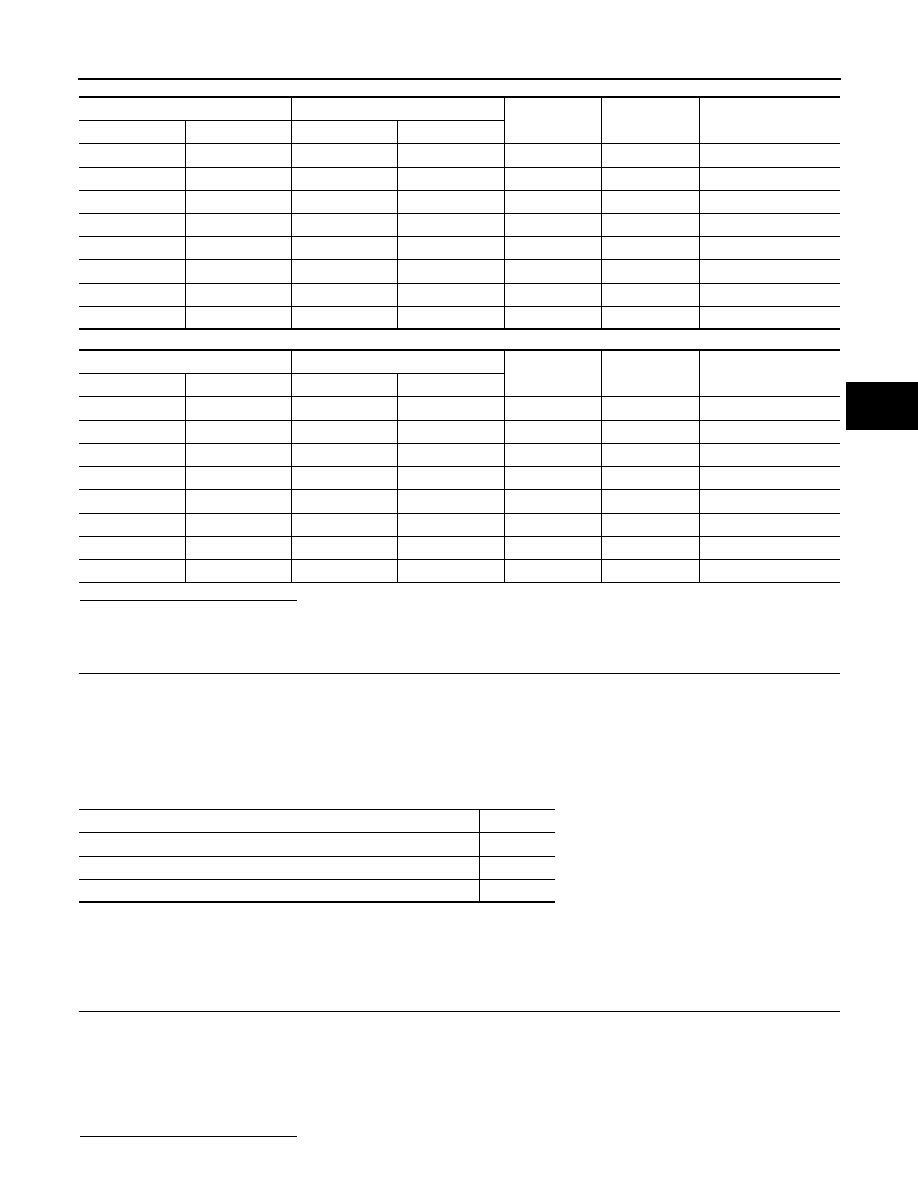
Brake ECU
Wheel sensor
—
Condition
Specified condition
Connector
Terminal
Connector
Terminal
E60
30
E41
1
—
Always
Below 1
Ω
E60
30
—
—
Ground
Always
10 k
Ω or higher
E60
17
E41
2
—
Always
Below 1
Ω
E60
17
—
—
Ground
Always
10 k
Ω or higher
E61
79
B43
3
—
Always
Below 1
Ω
E61
79
—
—
Ground
Always
10 k
Ω or higher
E61
66
B43
4
—
Always
Below 1
Ω
E61
66
—
—
Ground
Always
10 k
Ω or higher
Brake ECU
Wheel sensor
—
Condition
Specified condition
Connector
Terminal
Connector
Terminal
E61
76
E19
1
—
Always
Below 1
Ω
E61
76
—
—
Ground
Always
10 k
Ω or higher
E61
64
E19
2
—
Always
Below 1
Ω
E61
64
—
—
Ground
Always
10 k
Ω or higher
E60
34
B43
1
—
Always
Below 1
Ω
E60
34
—
—
Ground
Always
10 k
Ω or higher
E60
33
B43
2
—
Always
Below 1
Ω
E60
33
—
—
Ground
Always
10 k
Ω or higher
Condition
Proceed to
DTCs (C1235, C1236, C1238 and/or C1239) are output (for front).
A
DTCs (C1235, C1236, C1238 and/or C1239) are output (for rear).
B
DTCs (C1235, C1236, C1238 and/or C1239) are not output.
C