Nissan Altima HL32 Hybrid. Instruction - part 20


  Index      Nissan     Nissan Altima HL32 Hybrid (2009 year) - Service and Repair Instruction


Search            copyright infringement  


Content   ..  18  19  20  21   ..


Nissan Altima HL32 Hybrid. Instruction - part 20


AV-72

< COMPONENT DIAGNOSIS >

[BOSE AUDIO WITHOUT NAVIGATION]

POWER SUPPLY AND GROUND CIRCUIT

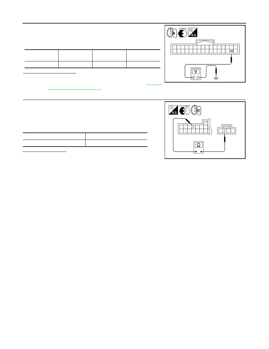
1. Connect Bluetooth control unit connector.

2. Turn ignition switch ON.

3. Check voltage between Bluetooth control unit harness connec-

tor and ground.

Is proper voltage present?

YES

>> Inspection End.

NO

>> Replace Bluetooth control unit. Refer to 

AV-145,

"Removal and Installation"

.

4.

CHECK GROUND CIRCUIT

1. Turn ignition switch OFF.

2. Disconnect Bluetooth control unit and microphone connectors.

3. Check continuity between microphone harness connector R7

terminal 2 and Bluetooth control unit harness connector B126

terminal 8. 

Is continuity present?

YES

>> Inspection End.

NO

>> Repair harness or connector.

Connector No.

Terminal No.

Ignition switch po-

sition

Value (Approx.)

B126

29

ON

5V

ALNIA0133ZZ

Signal name

Continuity

Microphone ground

Continuity should exist.

ALNIA0170ZZ

AV

FRONT DOOR SPEAKER

AV-73

< COMPONENT DIAGNOSIS >

[BOSE AUDIO WITHOUT NAVIGATION]

C

D

E

F

G

H

I

J

K

L

M

B

A

O

P

FRONT DOOR SPEAKER

Description

INFOID:0000000004219442

The audio unit sends audio signals to the BOSE speaker amp. The BOSE speaker amp. amplifies the audio

signals before sending them to the front door speakers using the audio signal circuits.

Diagnosis Procedure

INFOID:0000000004219443

1.

HARNESS CHECK

1. Disconnect BOSE speaker amp. connector B121 and suspect

speaker connector.

2. Check continuity between BOSE speaker amp. harness connec-

tor B121 (A) and suspect speaker harness connector (B).

3. Check continuity between BOSE speaker amp. harness connec-

tor B121 (A) and ground.

Are continuity test results as specified?

YES

>> GO TO 2

NO

>> • Check connector housings for disconnected or loose terminals.

• Repair harness or connector.

2.

FRONT SPEAKER SIGNAL CHECK

Terminals

Continuity

A B

Connector

Terminal

Connector

Terminal

B121

58

D3

1

Yes

59

2

71

D103

1

72

2

Terminals

Continuity

A

B

Connector

Terminal

B121

58

Ground

No

59

71

72

ALNIA0134ZZ

AV-74

< COMPONENT DIAGNOSIS >

[BOSE AUDIO WITHOUT NAVIGATION]

FRONT DOOR SPEAKER

1. Connect BOSE speaker amp. connector B121 and suspect

speaker connector.

2. Turn ignition switch to ACC.

3. Push “POWER” switch.

4. Check the signal between BOSE speaker amp. harness connec-

tor B121 terminals with CONSULT-III or oscilloscope.

Is audio signal voltage as specified?

YES

>> Replace suspect speaker. Refer to 

AV-134, "Removal

and Installation"

.

NO

>> GO TO 3

3.

HARNESS CHECK

1. Disconnect audio unit connector M43 and BOSE speaker amp.

connector B121.

2. Check continuity between audio unit harness connector M43 (A)

and BOSE speaker amp. harness connector B121 (B).

3. Check continuity between audio unit harness connector M43 (A)

and ground.

Are continuity test results as specified?

YES

>> GO TO 4

NO

>> • Check connector housings for disconnected or loose terminals.

• Repair harness or connector.

4.

FRONT SPEAKER SIGNAL CHECK

Connec-

tor

Terminal

Condition

Reference

signal

(+)

(-)

B121

58

59

Receive 
audio sig-
nal

71

72

ALNIA0135ZZ

SKIA0177E

Terminals

Continuity

A

B

Connector

Terminal

Connector

Terminal

M43

2

B121

75

Yes

3

76

11

73

12

74

Terminals

Continuity

Connector

Terminal

M43

2

Ground

No

3

11

12

ALNIA0136ZZ

AV

FRONT DOOR SPEAKER

AV-75

< COMPONENT DIAGNOSIS >

[BOSE AUDIO WITHOUT NAVIGATION]

C

D

E

F

G

H

I

J

K

L

M

B

A

O

P

1. Connect audio unit connector and BOSE speaker amp. connec-

tor.

2. Turn ignition switch ACC.

3. Push “POWER” switch.

4. Check the signal between audio unit harness connector termi-

nals with CONSULT-III or oscilloscope.

Are the audio signal voltage readings as specified?

YES

>> Replace BOSE speaker amp. Refer to 

AV-131,

"Removal and Installation"

.

NO

>> Replace audio unit. Refer to 

AV-130, "Removal and

Installation"

.

Connector

Terminals

Condition

Reference

signal

(+)

(-)

M43

2

3

Receive 
audio sig-
nal

11

12

ALNIA0171ZZ

SKIA0177E


Content   ..  18  19  20  21   ..