Nissan Frontier. Instruction - part 781
PARKING LAMP CIRCUIT
EXL-49
< DTC/CIRCUIT DIAGNOSIS >
C
D
E
F
G
H
I
J
K
M
A
B
EXL
N
O
P
Are continuity results as specified?
YES
>> Replace IPDM E/R. Refer to
PCS-28, "Removal and Installation of IPDM E/R"
.
NO
>> Repair the harnesses or connectors.
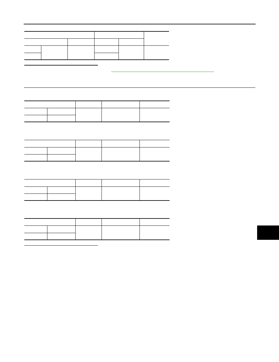
4.
CHECK PARKING, LICENSE AND TAIL LAMP GROUND CIRCUITS
1. Check continuity between the front combination lamp harness connector and ground.
2. Check continuity between the front side marker lamp harness connector and ground.
3. Check continuity between the rear combination lamp harness connector and ground.
4. Check continuity between the license plate lamp harness connector and ground.
Are continuity results as specified?
YES
>> Inspect the parking lamp bulb.
NO
>> Repair the harness.
IPDM E/R
License plate lamp
Continuity
Connector
Terminal
Connector
Terminal
LH
E124
57
C203
1
Yes
RH
C204
Connector
Terminal
—
Continuity
LH
E27
4
Ground
Yes
RH
E111
Connector
Terminal
—
Continuity
LH
E17
8
Ground
Yes
RH
E108
Connector
Terminal
—
Continuity
LH
C201
2
Ground
Yes
RH
C202
Connector
Terminal
—
Continuity
LH
C203
2
Ground
Yes
RH
C204