Nissan Frontier. Instruction - part 762
ENGINE UNIT
EM-237
< UNIT DISASSEMBLY AND ASSEMBLY >
[VQ40DE]
C
D
E
F
G
H
I
J
K
L
M
A
EM
N
P
O
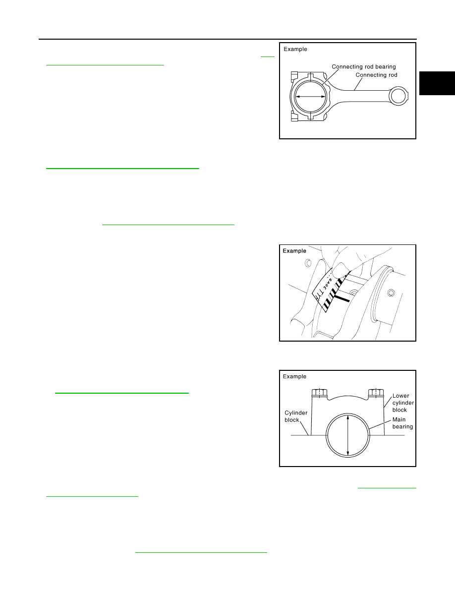
• Install connecting rod bearings to connecting rod and cap, and
tighten connecting rod bolts to the specified torque. Refer to
220, "Disassembly and Assembly"
• Measure the inner diameter of connecting rod bearing with inside
micrometer.
(Bearing oil clearance) = (Connecting rod bearing inner diameter) –
(Crankshaft pin journal diameter)
• If the calculated value exceeds the limit, select proper connecting rod bearing according to connecting rod
big end diameter and crankshaft pin journal diameter to obtain the specified bearing oil clearance. Refer to
EM-242, "How to Select Piston and Bearing"
Method of Using Plastigage
• Remove oil and dust on crankshaft pin journal and the surfaces of each bearing completely.
• Cut plastigage slightly shorter than the bearing width, and place it in crankshaft axial direction, avoiding oil
holes.
• Install connecting rod bearings to connecting rod and cap, and tighten connecting rod bolts to the specified
EM-220, "Disassembly and Assembly"
for the tightening procedure.
CAUTION:
Do not rotate crankshaft.
• Remove connecting rod bearing cap and bearing, and using scale
on plastigage bag, measure the plastigage width.
NOTE:
The procedure when the measured value exceeds the limit is
same as that described in the “Method by Calculation”.
MAIN BEARING OIL CLEARANCE
Method by Calculation
• Install main bearings to cylinder block and lower cylinder block,
and tighten lower cylinder block bolts to the specified torque. Refer
to
EM-220, "Disassembly and Assembly"
for the tightening proce-
dure.
• Measure the inner diameter of main bearing with bore gauge.
(Bearing clearance) = (Main bearing inner diameter) – (Crankshaft
main journal diameter)
• If the calculated value exceeds the limit, select proper main bearing according to main bearing inner diame-
ter and crankshaft main journal diameter to obtain specified bearing oil clearance. Refer to
.
Method of Using Plastigage
• Remove engine oil and dust on crankshaft main journal and the surfaces of each bearing completely.
• Cut plastigage slightly shorter than the bearing width, and place it in crankshaft axial direction, avoiding oil
holes.
• Install main bearings to cylinder block and lower cylinder block, and tighten lower cylinder block bolts to the
specified torque. Refer to
EM-220, "Disassembly and Assembly"
for the tightening procedure.
CAUTION:
Standard
: 0.034 - 0.059 mm (0.0013 - 0.0023 in) (actu-
al clearance)
Limit
: 0.070 mm (0.0028 in)
PBIC1642E
PBIC1149E
Standard
: 0.035 - 0.045 mm (0.0014 - 0.0018 in)
(actual clearance)
Limit
: 0.065 mm (0.0026 in)
PBIC2204E